lancer 600 LFCV Series Installation And Service Manual Download Page 18

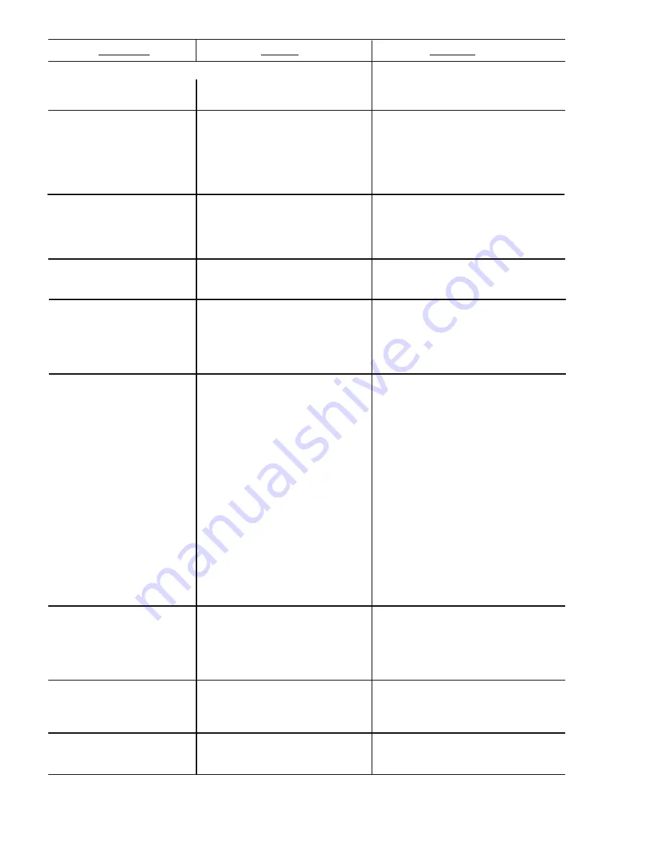
Section 8.17 continued from previous page.

F. Refrigerant leak.

F. Repair and recharge.

G. Compressor malfunctioning.

G. Replace compressor.

8.18

Compressor runs

A. Low water level in water

A. Add water to water bath until water

normally, but water

bath.

runs out of overflow into drip tray.

line is frozen.

B. Syrup in water bath.

B. Drain water from water bath and

refill with clean water.

C. Water cage is out of position.

C. Reposition water cage.

D. Low refrigerant charge/slow

D. Find and repair leak.  Recharge

refrigerant leak

system.

8.19

Compressor cycles

A. PCB malfunctioning

A. Replace PCB assembly.

on and off frequently

B. Defective probe.

B. Replace probe.

during the initial

C. Air flow blocked.

C. Check to ensure proper air

pulldown and/or

clearance is provided (see 

normal operations.

Section 1.4).

8.20

Plain water flow is

A. Insufficient incoming supply

A. Verify incoming supply water

insufficient.

water and/or pressure.

pressure is a minimum of zero (0)

PSI flowing.

8.21

Suspect faulty PCB.

A. PCB not receiving proper

A. Check power from transformer on

input voltage.

pins 4 and 5 of J10.

B. Green light not flashing (off

B. Replace PCB.

or continuously on).

C. Yellow lights off and green light C. Check fuses F1 and F2, and also

is on when key switch is on.

connection at J10.

8.22

Circuit breaker tripping.

A. Pump is shorted.

A. Disconnect pump and restore

power.  If breaker does trip, then

pump is OK.  If breaker does not

trip, replace pump.

B. Refrigeration relay is bad.

B. Detect short by disconnecting J10

connector (24VAC input) from

PCB.  Restore power.  If breaker

doesn’t trip, then replace

refrigeration relay.  If breaker does

trip, then refrigeration relay is OK. 

Reconnect J10 connector.

C. Secondary wire harness is

C. Detect short by disconnecting both

bad.

secondary transformer fastons and

restore power.  If it does not trip,

locate short in secondary harness

between transformer and PCB.

D. Transformer failure.

D. Detect short by disconnecting both

primary transformer fastons and

restore power.  If breaker doesn’t

trip, replace transformer.

8.23

BIB pump does not

A. Out of CO

2

, CO

2

not turned

A. Replace CO

2

supply, turn on CO

2

operate when

on, or low CO

2

pressure.

supply, or adjust CO

2

pressure to

dispensing valve is

70-80 PSI.

opened.

B. Out of syrup.

B. Replace syrup supply.

C. BIB connector not tight.

C. Fasten connector tightly.

D. Kinks in syrup or gas lines.

D. Straighten or replace lines.

8.24

BIB pump operates but

A. Leak in syrup inlet or outlet

A. Replace line.

no flow.

line.

B. Defective BIB pump check

B. Replace BIB pump.

valve.

8.25

BIB pump continues to

A. Leak in suction line.

A. Replace line.

operate when bag is

B. Leaking o-ring on pump inlet

B. Replace o-ring.

empty.

fitting.

15

TROUBLE

CAUSE

REMEDY

Summary of Contents for 600 LFCV Series

Page 1: ...e of 70 PSIG 4 92 kg cm2 4 83 BAR Maximum pressure of 80 PSIG 5 62 kg cm2 5 52 BAR ICE BANK WEIGHT 11 to 13 pounds 5 0 to 5 9 kg INSTALLATION AND SERVICE MANUAL LANCER SERIES 600 LFCV COLD CARBONATED...

Page 2: ...line voltage consider installing a surge protector or similar protection device 4 There is a five 5 minute delay which prevents the compressor and condenser fan from starting until the delay has laps...

Page 3: ...WARM DRINKS 13 8 13 COMPRESSOR DOES NOT START NO HUM CONDENSER FAN MOTOR DOES NOT RUN AND NO ICE BANK 14 8 14 COMPRESSOR DOES NOT START NO HUM BUT CONDENSER FAN MOTOR RUNS 14 8 15 COMPRESSOR DOES NOT...

Page 4: ...aim against same B Each kit contains a list of the parts and a drawing showing the proper assembly of the parts 1 4 SELECTING A COUNTER LOCATION A Select a location close to a properly grounded electr...

Page 5: ...al current available C Route the power supply cord to a grounded electrical outlet of the proper voltage and amperage rating and plug in the unit This will turn on the refrigeration system and allow i...

Page 6: ...HOULD BE USED A Remove the protective caps from the syrup pump inlets and connect syrup inlet tube assemblies furnished in the installation kit to the syrup pumps Lubricate o rings before installation...

Page 7: ...2 cylinder and observe if the pressure to the system drops with the cylinder valve closed for five 5 minutes Open the cylinder valve after check G Replace the unit s top cover splash plate and cup res...

Page 8: ...dure CAUTION BE CAREFUL NOT TO GET SANITIZING SOLUTION ON THE CIRCUIT BOARD a Disconnect power so the valve will not be inadvertently activated while cleaning b Remove nozzle housing by twisting it co...

Page 9: ...ft side in any configuration The small button on the top left will always dispense soda and the large button on the bottom left will always dispense plain water 6 Membrane Switch Panel Configuration F...

Page 10: ...ual flavor switches will operate manually if no size selection is made A PROGRAMMING PROCEDURE 1 To turn the Portion Control feature on enter the programming mode by simultaneously pressing and holdin...

Page 11: ...justing the syrup flow control Recheck as necessary F Repeat process for other syrup modules plumbed to the nozzle G Remove separator replace nozzle and repeat for other nozzle H After all modules are...

Page 12: ...ing solution visually inspect around the nozzle mounting area on the valve for syrup residue Using a cloth or nozzle brush and warm water clean this area 6 Wipe off the valve shroud assembly and any o...

Page 13: ...the end of the nozzle body assembly if necessary 3 Apply 111 Lubricant to o ring as required 4 Install nozzle housing by inserting it onto the nozzle body and twisting it in a clockwise direction to l...

Page 14: ...e dispenser Periodically according to the local water quality the screen should be removed and cleaned A To clean the screen remove the water pump B Remove screen from the outlet port C Clean screen a...

Page 15: ...eset circuit breaker on top of interrupted control box If breaker trips again refer to Section 8 22 Also check connection J10 on circuit board and check Fuse F2 on PCB E Valves not receiving power E C...

Page 16: ...ty ice D Check quality of ice used in drink E High beverage temperature E Check refrigeration system 8 10 Water continually A Loose water connection s A Tighten water connection s overflows from water...

Page 17: ...C Incorrect wiring C Refer to wiring diagram and correct D Compressor malfunctioning D Replace compressor 8 15 Compressor does not A Inadequate voltage A Measure voltage across common start but hums a...

Page 18: ...n connection at J10 8 22 Circuit breaker tripping A Pump is shorted A Disconnect pump and restore power If breaker does trip then pump is OK If breaker does not trip replace pump B Refrigeration relay...

Page 19: ...o CO2 A Check CO2 supply Adjust CO2 pressure to 70 PSI B Excessive water pressure B Water regulator should be set at 50 PSI C Low water pressure C Must be 25 PSIG flowing with carbonator pump running...

Page 20: ...41 19 21 16 15 14 11 25 48 49 7 4 3 33 40 44 45 46 37 42 31 29 22 8 32 18 38 20 17 27 34 35 36 28 10 13 47 39 12 43 30 6 2 1 5 17 9 ILLUSTRATIONS PARTS LISTINGS AND WIRING DIAGRAMS 9 1 COMPRESSOR DEC...

Page 21: ...1 0061 Accumulator 0 375 Holes 23 30 6844 Retainer Baffle Condenser 600 24 50 0322 Baffle Condenser Side 600 25 50 0325 Baffle Condenser Top 600 26 04 0518 Rivet 0 125 DIA x 0 328 LG DH 27 02 0040 Sea...

Page 22: ...9 2 MINIPUMP ASSEMBLY FIVE FLAVOR PN 82 3095 FOUR FLAVOR 82 3095 04 1 3 4 6 5 7 8 9 3 3 10 11 11 13 12 17 6 16 18 9 15 10 10 5 9 14 7 3 5 2 19...

Page 23: ...0029 Tubing Inner Braided 0 250 ID x 0 437 OD 7 01 1483 Elbow Assy Syrup 1 4 Barb 8 01 0222 Nut Swivel 7 16 20 9 07 0441 Clamp Oetiker 9 32 10 08 0036 Tube CO2 11 04 0359 Screw 8 32 x 3 100 12 02 0005...

Page 24: ...8 16 22 23 21 19 26 18 24 25 27 28 20 25 30 29 7 6 15 5 15 9 26 15 26 10 11 12 13 25 1 2 14 3 17 4 15 9 3 SERIES 600 LFCV CABINET ASSEMBLY 21...

Page 25: ...0097 Key Switch Optional 05 1502 Plug Key Hole 18 54 0271 Shroud Assy 19 05 1360 Plate Valves 20 05 1464 Pin Hinge Shroud Assy 21 05 1465 Arm Hinge Shroud Assy 22 12 0281 01 Membrane Switch 23 04 0571...

Page 26: ...212 Pump Assy Carbonator 2 02 0047 O Ring 3 17 0512 Valve Assy Ball Water Inlet 4 02 0089 O Ring 5 48 1795 Tube Assy Inlet Ball Valve 6 48 1674 Tube Assy Inlet Pump Inlet 7 30 6865 Mount Carbonator Mo...

Page 27: ...4 0477 Screw 8 32 x 0 375 7 52 2594 Lead Assy Fan Motor 8 52 2595 Lead Assy Agitator Motor 9 52 2597 Lead Assy Comp 2 10 52 2208 Lead Assy Comp 1 11 52 2596 Lead Assy 5 Pin Control 52 2365 Lead Assy S...

Page 28: ...9 11 13 15 2 14 3 16 15 15 12 9 8 1 7 6 5 4 10 17 9 9 9 9 6 SERIES 600 LFCV CARBONATOR WATER SYRUP LINE ASSEMBLIES 25...

Page 29: ...48 1851 Tube Assy Syrup 4 without Pumps 8 48 1811 Tube Assy Syrup 5 with Pumps 48 1852 Tube Assy Syrup 5 without Pumps 9 02 0005 O Ring 10 23 1259 Cage Assy 11 48 1405 Tube Assy Water Option 12 17 03...

Page 30: ...fi LABEL WIRING DIAGRAM 06 2514 B SWITCH B POWER BREAKER CIRCUIT B B B B W 2 MOTOR FAN 2 1 1 B B W MOTOR AGITATOR B W B B W P R I S E C B W COMPRESSOR B B W B W B W B W B W COMPRESSOR T4 T6 T8 T10 T3...

Page 31: ...B 7 Pannalal Silk Mill Compounds 78 LBS Marg Bhandup W Mumbai 400 078 India Phone 91 22 2561 6665 Cel No 91 98 2029 5252 FAX 91 22 5637 4018 e mail shafiquis vsnl com Lancer Authorized Distributors W...

Page 32: ...as Villas San Nicolas De Los Garza N L Monterrey N L M xico C P 66422 Phone 52 81 83 52 85 32 Phone 52 81 83 52 85 34 Phone 52 81 83 52 53 60 FAX 52 81 83 32 54 10 e mail direccion lancer com mx Lance...

Reviews: