10
ILLUSTRATIONS & DIAGRAMS
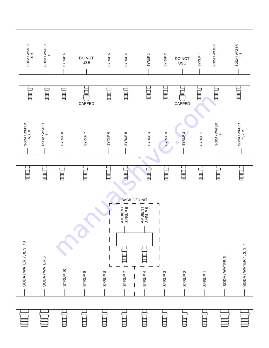
2300, 6 Valve, Standard Plumbing Diagram
2300, 8 Valve, Standard Plumbing Diagram
2300, 10 Valve, Standard Plumbing Diagram
Page 1: ...or instruction concerning use of the appliance by a person responsible for their safety Cleaning and user maintenance shall not be performed by children without supervision The min max ambient operati...
Page 2: ...tion and operation of this dispenser If service is required please call your Lancer Service Agent or Lancer Customer Service Always have your model and serial number available when you call READ THIS...
Page 3: ...Counter Location The installation and relocation if necessary must be carried out by qualified personnel with up to date knowledge and practical experience in accordance with current regulations NOTE...
Page 4: ...using oetiker pliers and fittings see Plumbing Diagrams on the front of the unit or on pages 10 11 for reference 13 Route appropriate tubing from the syrup pump location through the shipping riser leg...
Page 5: ...in 22 Install power supply assembly to bottom plate of free standing conversion kit or under counter 23 Route the power supply cord to a grounded electrical outlet of the proper voltage and amperage r...
Page 6: ...r fatal electrical shock The power cord has a three prong grounded plug If a three hole grounded electrical outlet is not available use an approved method to ground the unit Follow all local electrica...
Page 7: ...e there is ice on the cold plate and the lines are cold before attempting to set the flow rates on the valves The drink temperature should be no higher than 40 F 4 4 C when flow rates are set NOTE A B...
Page 8: ...precautions DO NOT use a water jet to clean or sanitize the unit DO NOT disconnect water lines when cleaning and sanitizing syrup lines to avoid contamination DO NOT use strong bleaches or detergents...
Page 9: ...h warm water and flush out syrup remaining in the lines 4 Prepare Cleaning Solution described on previous page Following sanitation rinse with end use product until there is no aftertaste Do not use a...
Page 10: ...10 ILLUSTRATIONS DIAGRAMS 2300 6 Valve Standard Plumbing Diagram 2300 8 Valve Standard Plumbing Diagram 2300 10 Valve Standard Plumbing Diagram...
Page 11: ...TIONAL Right Side Bin Switch Right Side Key Switch LEFT BANK OF VALVES RIGHT BANK OF VALVES CENTER BANK OF VALVES Right Side Power Supply Left On Top Right On Bottom Key Switch Orientation Wall Outlet...
Page 12: ...CUTOUT 23 1 4 591 mm 25 5 648 mm 2300 Counter Cutout Diagram To prevent possible harm to the environment from improper disposal recycle the unit by locating an authorized recycler or contact the retai...