Measurement information:
Strip
con-
nector
MEASUREMENTS
Additional information
Putting sensor into use and removing it from use:
If the outdoor sensor is not connected, the regulator assumes that the outdoor temperature is
0°C and a sensor fault message appears on the display (Outdoor temp err). When the outdoor
sensor is connected, the regulator automatically takes it into use.
(See page 16)
After adding other sensors
you must go to start function!
Resistance
value table
-30
-25
-20
-15
-10
-5
0
5
10
15
20
25
30
35
40
45
50
55
60
65
70
75
80
90
100
110
177 100
130 400
96 890
72 830
55 340
42 340
32 660
25 400
19 900
15 710
12 490
10 000
8 064
6 531
5 330
4 368
3 602
2 987
2 490
2 084
1 753
1 482
1 259
917
680
511
Measure-
ment:
Setting
range:
Attention!
°C
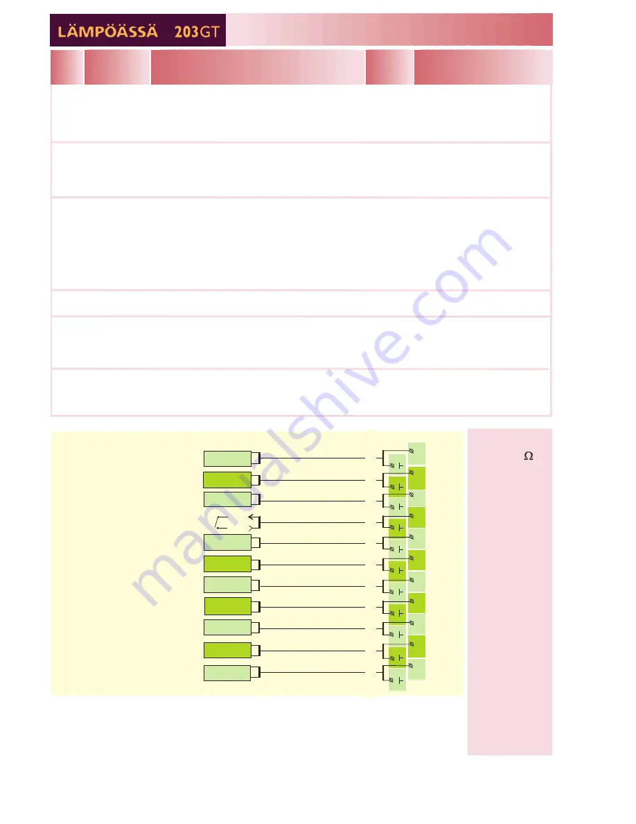
INSTRUCTIONS FOR CONNECTING SENSORS:
TMR
Free temp. measurement (Measure 11)
Compressor's upper part hot gas temp.
34
5
6
78
9
10
11
2 x 0.8
2 x 0.8
2 x 0.8
2 x 0.8
2 x 0.8
2 x 0.8
2 x 0.8
2 x 0.8
TMW or TMS
TMW or TMS
TMW or TMS
TMW or TMS
TMW or TMS
TMW or TMS
Meas.3
Meas.4
Meas.5
Meas.6
Meas.7
Meas.8
Meas.9
Meas.10
Meas.11
Meas.1
TMO
TMW or TMS
T1
1
T
1
1
1
2
2 x 0.8
2 x 0.8
2 x 0.8
Meas.2
Outdoor temp. sensor
H1 Supply water sensor
H1 Room sensor
H2 Supply water sensor
Free temp. measurement
(Measure 6)
HW supply water sensor
HW circulating water sensor
(anticipate -sensor)
Acc. upper part temperature sensor
1
Free measurement; name using the text editor
11
r position in regulating circuit HW
9
Acc.upp.part
Accumulator’s upper part temperature
11 Measure 11
ActuatorHW
Actuato
Out temp
2
H1 Supply
Supply
3
H1 Room
5
H2 Supply
Supply
6
Measure 6
H2 Room
6
Wind
6
Sun
7
HW supply
HW (d
8
HW circul.wat
10 Acc.low.part
Accumulator’s lower part temperature
Wat m3
ActuatorH1
Actuator
ActuatorH2
Actuator
Outdoor temperature
water temperature in regulating circuit H1
Room temp. in regulating circuit H1 (room comp.)
water temperature in regulating circuit H2
Free measurement; name using the text editor
6
Room temp. in regulating circuit H2 (room comp.)
Wind speed (% of sensor's range)
Amount of light (% of sensor's range)
omestic hot water) supply water temp.
Temp. measurement of HW return water.
(an anticip. sensor is used improve the setting
results, see page 21, Anticipate)
Measured water consumption of facility (m )
position in regulating circuit H1
position in regulating circuit H2
3
Hot gas
Temp. measured from compressor's upper part
Compr.Time
Compressor's total running time (running time
counter)
El.HeatTime
Electrical heating resistor's total running time in
hours (running time counter)
T1
T2
T3
T4
T5
T6
T7
T8
T9
T10
T1
1
TMW or TMS
Interchangeable (p. 31). If
several compens. are needed,
the data must be read through
the net and the wind is m/s
and the light is lux (p. 36).
Can be read through the net
-50...+50
0 . . . + 1 3 0
-10...+80
0 . . . + 1 3 0
-10...+80
0 . . . + 1 3 0
-10...+80
0 . . . + 1 3 0
0 . . . + 1 3 0
0 . . . + 1 3 0
0...99999,9
Can be read through the net
Measurement data through
a digital input or the bus.
Acc. lower part temperature sensor
10
Appears only when using a
0...10V (2...10V) controlled
actuator.
Compressor's running information


