background image


4


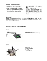
4-2. DESCRIPTION OF THE OPERATING ELEMENTS FRONT SIDE 


(Illus. 1) 


CHARGE LIGHT (1) 

Glows orange during charging 

OPERATION LIGHT (2) 

Glows yellow when ready for welding


WELD POWER DIAL (3) 

6 level adjustable welding power 

IMPULSE LENGTH SWITCH (4) 
CONNECTOR JACK FOR HAND PIECE (5) 
JACKS (6)  

For connecting the contact elements such as welding 
table, clamps and holding pliers 


4-3. DESRIPTION OF THE OPERATIONS ELEMENTS BACK SIDE 


(Illus. 2) 


FUSEBOX (7)


Fuse box with space for spare fuses 

MAINS POWER SWITCH (8) 
RECEPTACLE (9)  

For connecting the power cable


INERT GAS CONNECTOR (10) 

For a 

 6,0 mm pressure hose  

CONNECTOR JACK FOR WELDING SHIELD(11) 

To adjust level of eye protection of the welding safety 
shield 


Summary of Contents for optiwelder T1

Page 1: ...Operating Instructions Precision Welding Device optiwelder T1 and PUK Optic Device Lampert Werktechnik GmbH 230V...

Page 2: ...rer will not be liable for any damages which result from improper usage or treatment Please read the sections General Safety Rules and Personal Body Protection carefully before you start up the device...

Page 3: ...tanium and various NE metals and nickel alloys such as brass German silver monel or EVO Also suitable for precious metals and precious metals alloys Not approved for welding dentures Dentistry Any usa...

Page 4: ...The welding device is set by the manufacturer at 230V this means the device may due to the tolerance of 15 also be operated on a 220V power Devices that operate on a different power than 230V will be...

Page 5: ...ECTOR JACK FOR HAND PIECE 5 JACKS 6 For connecting the contact elements such as welding table clamps and holding pliers 4 3 DESRIPTION OF THE OPERATIONS ELEMENTS BACK SIDE Illus 2 FUSEBOX 7 Fuse box w...

Page 6: ...and set the gas flow to ca 3 6 liter per minute m a x i m u m operating pressure 10 bar Insert the power plug Switch the mains power switch 8 to ON the device will perform an automatic test The yellow...

Page 7: ...ng addition For deeply located welding spots the electrode should be longer It may be helpful to use wire as a welding addition to close holes or as reinforcement Only use welding wires as a welding a...

Page 8: ...RGON 99 9 ARGON 4 6 Maximum gas pressure 10 bar Inert class I Insulation class B Weight 5 20 kg 6 2 Identification Plate Symbol explanations Amperage Voltage Protection Method Hertz Alternating Curren...

Page 9: ...t im Leerlauf aus Install proper power protection Send device to be serviced 6 Welding unsatisfactory Wrong safety gas no inert gas Use inert gas Argon 4 6 7 Oxidation and soot development Gas pressur...

Page 10: ...EWG According to EMV electro magnetic compatibility guidelines 89 336 EWG The Manufacturer Lampert Werktechnik GmbH Julius Echter Str 4 97440 Werneck Germany declares that the product optiwelder T1 Sp...

Page 11: ...10...

Page 12: ...e for any damages which result from improper usage or treatment Please read the sections General Safety Rules and Personal Body Protection carefully before you start up the device Note The devices man...

Page 13: ...SAFETY RULES A professional may only open the device Remove the power plug and make sure the device is not under live power Always contact your professional if you are uncertain Before replacing the e...

Page 14: ...ON The view protection filter 2 must switch from dark to bright shortly after turning on the device for a test Perform this test every time before you begin working with this device to make sure it is...

Page 15: ...ation unit welding shield only to be operated with the Opti Welder Precision welding device Use only in dry environments Operating temperature 5 C to 40 C Mains Voltage 15 230 V 50 60 Hz Illumination...

Reviews: