START UP AND INSTRUCTIONS
Insert the welding shield into the lamp holder (3)
Install the illumination bulb (max. 9W) into the
provided socket
Plug in the lamp’s connector plug (4) into the outlet
(5) on the rear side of the welding device and fasten
by carefully turning per hand towards the right.
Plug in the welding shield’s power plug (6) into an
appropriate ~230 V (22V) / 50-60 Hz. power outlet.
Keep a minimum distance of 15 cm between the
illumination and/or the work piece and welding
table.
Turn the power switch (1) to „ON“
The view protection filter (2) must switch from dark to
bright shortly after turning on the device for a test.
Perform this test every time before you begin
working with this device to make sure it is in perfect
working condition. If necessary, start the test over by
turning off the device and turning it back on after a
few moments.
ATTENTION!
Always test that the Welding Shield is in correct functioning order before you start
welding. If the glare protection filter (Shutter) does not switch from bright to dark, it
must immediately be replaced.
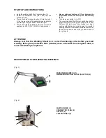
DESCRIPTION OF THE OPERATING ELEMENTS
(Fig. 1)
MAIN POWER SWITCH (1)
GLARE PROTECTION FILTER (SHUTTER (2)
(Fig. 2)
3
4
5
6
LAMP HOLDER (3)
CONNECTOR PLUG (4)
OUTLET (5)
POWER CABLE (6)
Summary of Contents for optiwelder T1
Page 11: ...10...


