


3.5.3 Sensor Lead Cable
59
|
www.lakeshore.com
3.5.3 Sensor Lead Cable
The sensor lead cable used outside the cooling system can be much different from
what is used inside. Between the instrument and vacuum shroud, heat leak is not a
concern. In this case, choose cabling to minimize error and noise pick up. Larger con-
ductor, 22 AWG to 28 AWG stranded copper wire is recommended because it has low
resistance yet remains flexible when several wires are bundled in a cable.
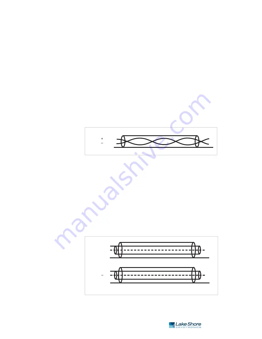
The arrangement of wires in a cable is also important. For the best results when inter-
facing to the control input, the voltage leads, V+ and V- should be twisted together
and current leads I+ and I- should be twisted together. The twisted pairs of voltage
and current leads should then be covered with a braided or foil shield that is con-
nected to the shield pin of the instrument. This type of cable is available through local
electronics suppliers. Instrument specifications are given assuming 3 m (10 ft) of sen-
sor cable.
While the above control input cabling description is also applicable for the minimum
cable configuration of the measurement input, it is recommended that the measure-
ment input voltage and current pairs be individually shielded. However, for maximum
performance, especially when measuring resistance above 100 k
)
, it is recom-
mended to use the driven guard configuration as described in section 3.5.4.
FIGURE 3-5 shows the recommended measurement input cable configuration.
3.5.4 Driven Guards
A configuration of guarded and shielded cables is shown below and is recommended
for long cables or when measuring large resistances. Variations may be necessary
depending on the configuration of available triaxial cable. Guards are tied only to the
guard pins on the measurement input connectors and should never be tied together,
tied to shields or terminated in any other way. They should always be left unattached
at the resistor end of the cable. The cable shield is tied to the shield pins on the mea-
surement input connectors. Section 3.5.6 explains how the shield can be extended to
the experimental Dewar without creating ground loops. The guards themselves pro-
vide some shielding, but they are not as effective as shields at reducing induced noise.
The driven guards are only available for the measurement input and are always
active. If you do not wish to use guarding, ensure that the guard conductors of the
cable are not connected to the Model 372 guard pins.
FIGURE 3-5
Twisted shield cables
(typical for measurement input current and voltage leads)
Pin Name
Shield
5
1
6
FIGURE 3-6
Measurement input guarded shielded cables
(typical for current and voltage leads)
Pin Name
Shield
G+
+
4
5
6
Pin Name
2
1
3
Shield
G–