21
3)
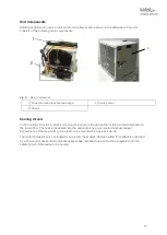
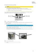
Open the coolant container by removing the cap.
4)
Fill the coolant container with about 3.7 liters of water or water/glycol mixture.
5)
Close the coolant container by fitting the cap.
Electrical Connections
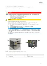
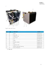
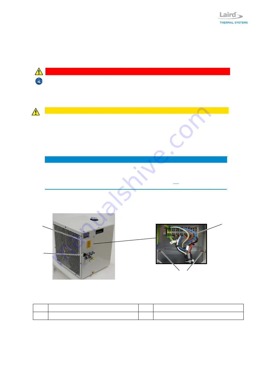
Fig. 10:
Electrical connections and terminal behind access plate
1
Electric terminal stripe
2 Earth bolt M5
3
Access plate
4 Cable bushings
DANGER
Danger to life through electrical shock when working on the electrical equipment of the unit!
Switch off the unit before starting your work!
Disconnect the unit from mains by pulling the mains plug!
Verify that the installation is dead (volt-free)!
Carry out earthing or short circuiting!
CAUTION
Risk of damage through improper connections!
Improper integration of the unit into the safety circuit of the device to be cooled will lead to the
inoperativeness of the safety equipment listed in chapter 3 on page 11.
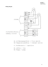
All connections required must be incorporated according to the wiring diagram shown in the
addendum.
Ensure yourself that all connected safety equipment is properly functioning.
All works should be carried out only by expert.
NOTE
The unit is delivered without a mains cable. The electrical connection as well as the integration into the
safety circuit of the device to be cooled are the customer’s responsibility and must be accomplished by
expert staff.
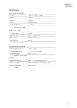
Required information can be drawn from the specifications listed on page
and the wiring diagram in
the addendum.
3
4
2
Summary of Contents for WL3004
Page 1: ...WL3004 Liquid to Air Cooling System Specification and User Manual Version 1 2 ...
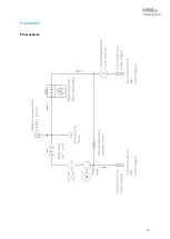
Page 35: ...35 Addendum Flow scheme ...
Page 36: ...36 Wiring diagram ...
Page 37: ...37 ...

