15
Unit Components
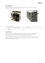
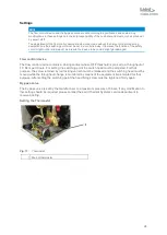
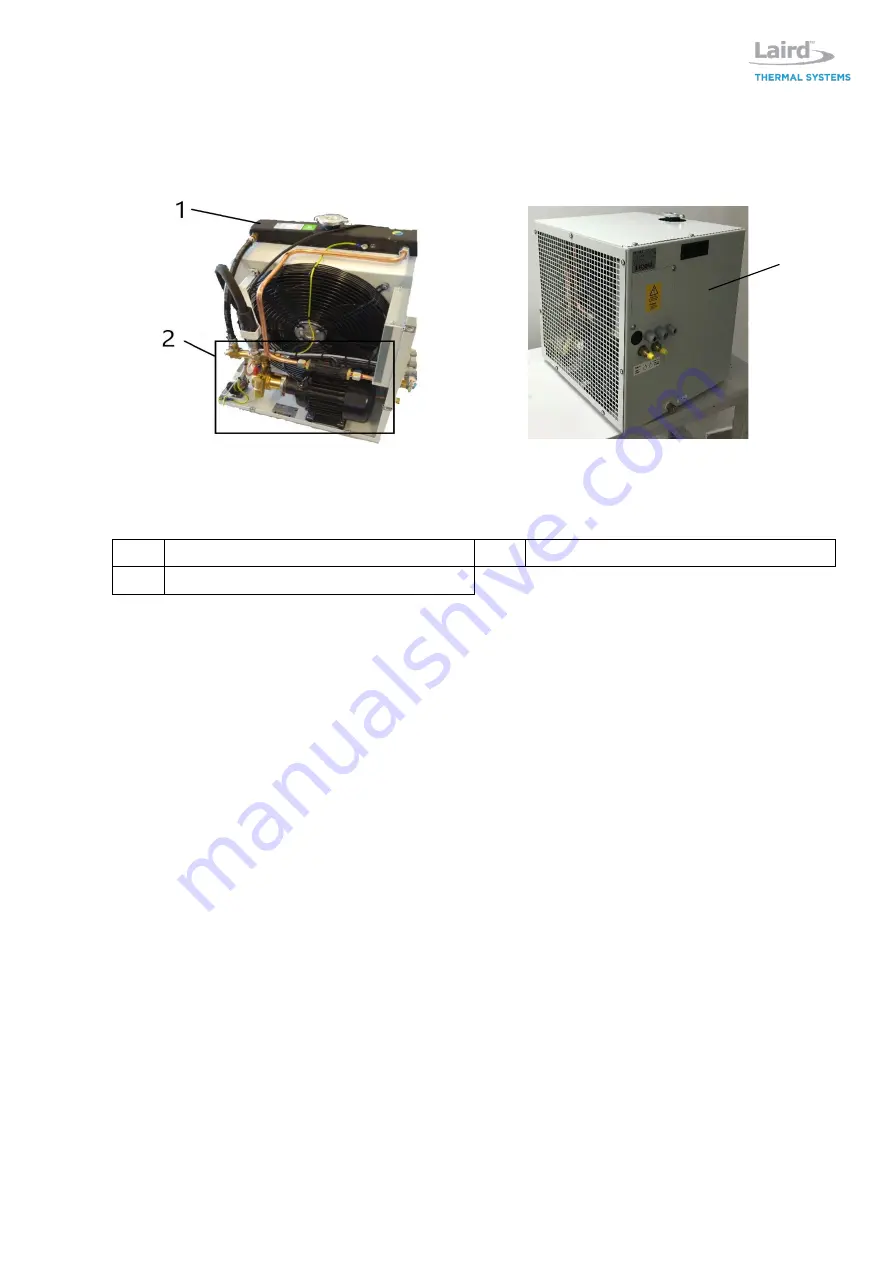
Additional information can be retrieved from the flow scheme shown in the addendum. The unit
consists of the following main components:
Fig. 6:
Main components
1 Coolant container and heat exchanger
2 Cooling circuit
3 Casing
Cooling Circuit
In the cooling circuit the coolant is driven by the pump to the device that is to be cooled and back via
the return flow. The heat is dissipated into the ambient air by an air-cooled heat exchanger.
Exceedance of the maximum pump pressure is prevented by a by-pass circuit.
The water temperature is controlled by an electric thermostat, whereas water throughput is controlled
by a flow control device. Both indications are made potential-free and must be integrated into the
safety circuit of the device to be cooled.
3
Summary of Contents for WL3004
Page 1: ...WL3004 Liquid to Air Cooling System Specification and User Manual Version 1 2 ...
Page 35: ...35 Addendum Flow scheme ...
Page 36: ...36 Wiring diagram ...
Page 37: ...37 ...


