12
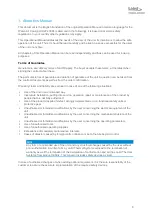
Guards
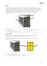
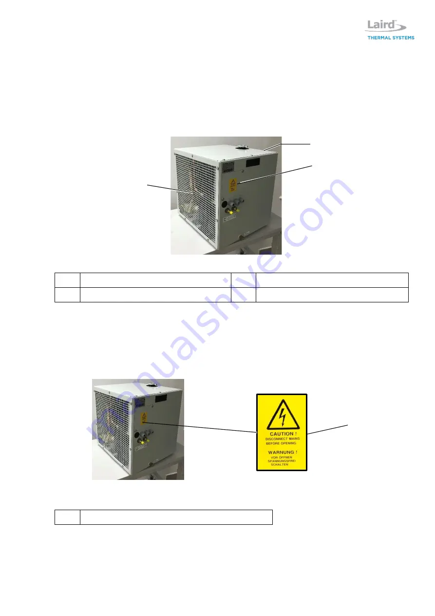
Direct access to hazardous parts or areas of the unit is restricted by the unit cover. The cover may
only be removed for the purpose of maintenance or repair works and shall be replaced prior to taking
the unit back into operation. The unit cover is fixed by 8 screws. The left-side panel can be removed
independently from the main cover by opening 7 quarter-turn fasteners. The electrical terminal area is
accessible after removing the corresponding plate on the front side held by two screws. For
unscrewing/screwing or opening/closing of the fasteners a 7.0 x 1.0 mm slotted screwdriver is
required.
Fig. 4:
Guards
1 Unit cover
2 Removable side panel
3 Access plate for electric terminal block
Caution Labels
Danger spots on the unit are indicated corresponding to German safety regulation BGV A8
"Sicherheits- und Gesundheitsschutzkennzeichnung am Arbeitsplatz".
Caution labels on the unit must be easily readable at all times. Illegible caution labels must be
exchanged without delay.
Fig. 5:
Caution labels on the unit
1 Hint on electrical hazardous area behind access plate
2
1
3
1
Summary of Contents for WL3004
Page 1: ...WL3004 Liquid to Air Cooling System Specification and User Manual Version 1 2 ...
Page 35: ...35 Addendum Flow scheme ...
Page 36: ...36 Wiring diagram ...
Page 37: ...37 ...


