background image


60 

$PCFLT 

(Returns [ FLT fault or “NO FAULTS FOUND”]) 

$PCFLT,C 

(Clears Fault, Returns [ FLT Faults Cleared]) 


Summary of Contents for Nextreme NRC1200 Series

Page 1: ...Nextreme Recirculating Chiller Specification and User Manual Part Number 387004848 ...

Page 2: ...g from use of or reliance on this information All Laird products are sold subject to the Laird Terms and Conditions of sale including Laird s limited warranty in effect from time to time a copy of which will be furnished upon request Copyright 2020 Laird Thermal Systems GmbH All Rights Reserved Laird Laird Technologies Laird Thermal Systems the Laird Logo and other word marks and logos are tradema...

Page 3: ...Markings 19 Optional System Features 20 Coolant Filter Kit 20 Flow Control Kit 21 Flow Control Kit with Filter 23 Transport Packaging and Storage 25 Safety 25 Checking the Delivery Condition 25 Symbols on the Packaging 25 Packaging 26 Unpacking 26 Handling the Unit While in the Packaging 28 Transportation on casters 29 Storing the Unit 29 Preparing the Unit for Further Transport 29 Installation Re...

Page 4: ...oting 54 Alarms 55 Communications Interface 59 Instructions for Setup 59 Commands and responses 59 Command entry format 59 Source ID 59 Command Structure Examples 59 System Maintenance and Service 61 Safety 61 Maintenance Schedule 62 Preparing the Unit for Maintenance 63 Verification of Safe State after Maintenance 63 Draining Procedure 64 Coolant Maintenance 65 Replace filter 65 Cleaning the Heat...

Page 5: ...5 Disposal of Operating Materials 70 Disposal of Refrigerant 71 Return of the Unit to Laird 71 Return Procedure 72 List of figures 73 ...

Page 6: ...6 Revision History REV DATE DESCRIPTION A 05 22 19 Initial Draft for EMC Testing B 10 16 2019 Manual for UL IEC Testing C 05 06 2020 Initial release for customer ...

Page 7: ...nalytical Instrumentation Industrial and Semiconductor This family of chillers offer different configurable options for pumps selection coolant flow control supply pressure monitoring and filtering This chiller also uses a semi closed system for low coolant maintenance This user manual provides necessary information to the customer for proper installation operation communication and maintenance of...

Page 8: ...ended purpose Conduct inspections on a regular basis and ensure the unit is operational and free of damage All unit warning and information signs must be kept in legible condition If a warning or information sign is lost or illegible it must be replaced Unit repairs may be carried out by qualified personnel only Any disruption or recognizable change concerning the unit should be reported to the re...

Page 9: ...manufacturer Operation in areas exposed to explosion hazards Operation without a cooling media not recommended by the manufacturer Any equipment connected to RS232 must be certified to IEC 61010 1 IEC 60950 1 IEC 62368 1 should be connected to the DB 9 port Only Laird approved cable must be used to connect Flow meter to the unit Refer to Spare Parts to order this cable High Temperature Limit on Co...

Page 10: ...uts off the entire unit Refrigerant leakage from the unit is detected by a low refrigerant suction pressure alarm in the unit When the refrigerant suction pressure falls below the pre set value the controller shuts off the entire unit The maximum pressure in the refrigeration system is limited by a refrigerant high pressure switch This switch is located on the compressor discharge line and switche...

Page 11: ...ing occurrences Fast vaporizing fluids can lead to frostbite Vapor is heavier than air and can lead to asphyxiation in enclosed poorly ventilated or low lying areas Misuse or intentional inhalation abuse may cause death without warning symptoms due to cardiac effects and may also cause arrhythmia Always adhere to manufacturer safety regulation when handling spilled refrigerant Environmental Issues...

Page 12: ... to groundwater and contains fluoridated greenhouse gas Do not release into canalization or waters Do not release into atmosphere Storage only in approved containers Waste disposal only by qualified contractors Always adhere to manufacturer safety requirements when handling operating supplies ...

Page 13: ...0 60Hz 20 220 230V 1ph 50 60Hz SC1 Stainless Centrifugal Pump SC2 Stainless Centrifugal Pump ST1 Stainless Turbine Pump H DI Water Compatible High Purity Notes System option codes are added to the end of the model number in alphabetical order Only available with NRC2400 and NRC5000 models only available with NRC1200 Only available with NRC5000 model See Laird Thermal Systems Online Wizard Configur...

Page 14: ...densing Operation Coolant Water or Water Glycol Temperature2 15 C to 40 C 59 F to 104 F Relative Humidity 30 to 80 Altitude 2 000 meters 6 560 feet Input Voltage 100 120 VAC or 220 230 VAC Frequency 50 60 Hz Physical Dimensions W x D x H 45 X 52 x 67 cm 17 7 x 20 5 x 26 4 in Weight w o coolant 48 kg 106 lbs Coolant Capacity 5 L 1 3 gal Couplings 1 2 NPT Compliance UL Mark for Laboratory Equipment ...

Page 15: ...g Operation Coolant Water or Water Glycol Temperature2 15 C to 40 C 59 F to 104 F Relative Humidity 30 to 80 Altitude 2 000 meters 6 560 feet Input Voltage 220 230 VAC Frequency 50 60 Hz Physical Dimensions W x D x H 48 X 52 x 75 cm 18 9 x 20 5 x 29 5 in Weight w o coolant 54 kg 119 lbs Coolant Capacity 5 L 1 3 gal Couplings 1 2 NPT Compliance UL Mark for Laboratory Equipment ANSI UL CSA IEC EN 61...

Page 16: ...tion Coolant Water or Water Glycol Temperature2 15 C to 40 C 59 F to 104 F Relative Humidity 30 to 80 Altitude 2 000 meters 6 560 feet Input Voltage 220 230 VAC Frequency 50 60 Hz Physical Dimensions W x D x H 63 x 59 x 91 cm 24 8 x 23 2 x 35 8 in Weight w o coolant 100 kg 220 lbs Coolant Capacity 5 L 1 3 gal Couplings 1 2 NPT Compliance UL Mark for Laboratory Equipment ANSI UL CSA IEC EN 61010 1 ...

Page 17: ...17 Component Locations Figure 2 Isometric Views of Unit Figure 3 Top View ...

Page 18: ...18 Figure 4 Front View Figure 5 Rear View Figure 6 Side View ...

Page 19: ...unit 6 Coolant supply label to the unit 7 Caution hazardous voltage label This label indicates location on the unit on the unit where power connections need to be made by the user Caution labels on the unit such as this must always be easily readable Illegible caution labels must be immediately replaced 8 Caution label temperature of the coolant into the system must not exceed 50 C 9 QR code for i...

Page 20: ...d the Filter can be put in bypass mode in order to change the cartridge without affecting flow Note For assembling the fittings use PTFE thread sealant tape provided with the kit to ensure a tight seal and to prevent leakage Figure 9 Coolant Filter Kit Part List Figure 10 Bypass mode of Filter Coolant Filter Kit assembled on Unit Bypass Mode ...

Page 21: ... parts The flow rate can be adjusted according to the application and can be monitored Refer Inadmissible Operating Conditions to avoid any safety hazards Note For assembling the fittings use PTFE thread sealant tape provided with the kit to ensure a tight seal and to prevent leakage Figure 11 Flow Control Kit Part List ...

Page 22: ...22 Assembly Instructions shown below Follow step numbers Figure 12 Assembly Instructions for Flow Control Kit Figure 13 Flow Control Kit assembled onto Unit ...

Page 23: ...sociated supporting parts Flow rate can be adjusted depending on the application and can be monitored and Coolant will be supplied through the filter Note For assembling the fittings use PTFE thread sealant tape provided with the kit to ensure a tight seal and to prevent leakage Figure 14 Flow Control Kit with Coolant Filter Parts List ...

Page 24: ...ollow step numbers Figure 15 Assembly Instructions for Flow Control Kit with Coolant Filter Coolant filter along with the Flow Control Kit fitted on the unit shown in picture Figure 16 Flow Control Kit with Coolant Filter assembled on Unit ...

Page 25: ...e Delivery Condition Check the delivery immediately upon receipt for possible transport damage and missing parts If any transport damage is noticed do the following Refuse the delivery or accept it with reservation Note extent of damage on the transport documents or on the delivery note Inform the manufacturer immediately of any damage incurred during transport Symbols on the Packaging The symbols...

Page 26: ...ned and recycled Dispose of packaging materials in an environmentally friendly way Follow the locally valid waste disposal regulations If necessary employ a special waste disposal company to dispose of packaging materials The unit is packed according to the anticipated transportation conditions such as packed in sealed plastic or cardboard box on a transport pallet The packaging function is to pro...

Page 27: ...27 b Lift the cardboard box and remove from the top c Carefully drop the fold down ramp to the floor d Remove the foam packing material Slide the plastic covering on the unit to the bottom ...

Page 28: ... Handling the Unit While in the Packaging WARNING Danger due to lifting and carrying heavy loads Manual handling of the loads lifting pushing and carrying must be avoided Unit weight Refer to Specifications Use only suitable means of transport such as industrial truck or lift truck WARNING Danger of injury due to tipping or falling loads Bruises Bone fracture When handling with industrial truck ob...

Page 29: ...nded rolling of the unit Place the unit on a level surface Lock the rollers brakes Storing the Unit These storage conditions apply to the following New units Units that were already in operation but will be temporarily out of operation Refer to Temporary Placing Out of Operation Store the units as follows Completely drained of coolant to prevent possible damage due to freezing Dry dust free enviro...

Page 30: ... the Coolant Coolant hoses disconnected from the unit Refer to Disconnecting the Coolant Hoses Procedure 1 Pack the unit according to the transport conditions that can be expected Laird advises to use original packaging if available or an equivalent packaging 2 Mark the packaging with the appropriate symbols Refer to Symbols on the Packaging The unit can now be transported ...

Page 31: ...ity Figure 17 Minimum Clearance required for Unit Installation 2 The location must be level 3 When choosing the installation location the following must be kept in mind a The flow of the cooling air must not be restricted b Coolant inlet and coolant outlet connections must be easily accessible c Power Cord must be easily accessible d All hoses must be installed without sharp bends ...

Page 32: ... to flow direction Follow the documentation released by the manufacturer of the unit to be cooled Transparent coolant hoses increase algae growth and bio fouling of the components in the unit and this reduces the performance of the unit Thus only use non transparent coolant hoses The coolant hoses are connected to the unit by means of couplings Coolant inlet and coolant outlet are labeled with res...

Page 33: ...led to the ambient temperature Required Tools and Materials Absorbent cloth Bonding agent Protection caps Procedure If the coolant inlet and outlet fittings have quick disconnects installed by the customer disconnect the hoses from coolant inlet and outlet fittings on the back of the unit If the coolant inlet and outlet fittings do not have quick disconnects or valves the system must be drained be...

Page 34: ...dding Coolant and Priming Unit The unit is not intended for use with corrosive fluids Automotive Antifreeze should never be used as a freezing point depression or corrosion protection fluid Automotive antifreeze contains additives that can damage system components and will void the warranty Approved fluids and their normal operating temperature ranges are Filtered Single Distilled water 10 C to 40...

Page 35: ...lling funnel Measuring cup Absorbent cloth Procedure 1 Remove the Fill Cap 2 For information regarding coolant to be used and quantity refer to Specifications Use a filling funnel to avoid moistening any current carrying components with coolant Note If refilling coolant go to last step 3 Add coolant up to required level Ideal coolant level is just below the HIGH marking on the front view port of t...

Page 36: ...the condenser coil and expansion valve are bypassed partially or completely The refrigerant flows through this loop for cases where the customer load is too low or where raising the temperature of the coolant is necessary to maintain stable application temperature 2 Coolant Circuit This circuit consists of the evaporator coolant tank pump and coolant Temperature of the coolant is regulated in the ...

Page 37: ...37 Figure 21 Refrigerant Circuit and Coolant Circuit Figure 22 Coolant Circuit and Control Panel ...

Page 38: ...38 Wiring Diagram Figure 23 Power Wiring Diagram High Voltage NRC2400 and NRC1200 230V Figure 24 Power Wiring Diagram High Voltage NRC5000 ...

Page 39: ...39 Figure 25 Sensor Wiring Low Voltage ...

Page 40: ...40 Plumbing Refrigeration Diagram Figure 26 Plumbing and Refrigeration Diagram ...

Page 41: ...ormance Graphs Thermal Performance NRC1200 Figure 27 Thermal Performance of NRC1200 with Cooling Fluids Water 40 EG W NRC2400 Figure 28 Thermal Performance of NRC2400 with Cooling Fluids Water 40 EG W NRC5000 ...

Page 42: ...42 Pump Performance NRC1200 Figure 29 Pump Performance of NRC1200 with Cooling Fluids Water 40 EG W NRC2400 Figure 30 Pump Performance of NRC2400 with Cooling Fluids Water 40 EG W NRC5000 ...

Page 43: ...43 Figure 31 Pump Performance of NRC5000 with Cooling Fluids Water and 40 EG W ...

Page 44: ...44 Chiller Dimensions Figure 32 NRC1200 Chiller Overall Dimensions Figure 33 NRC2400 Chiller Overall Dimensions ...

Page 45: ...45 Figure 34 NRC 5000 Chiller Overall Dimensions NOTE 1 Dimensions are in mm 2 Dimensions in parathesis are in inches ...

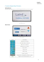
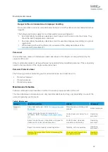
Page 46: ...seconds Figure 35 Start up Screen Main Screen Figure 36 Main Menu Buttons Description Main Menu is selected Information Menu is selected Alarm menu is selected Settings menu is selected Pump is OFF Pump is ON Chiller is OFF Chiller is running Pump Button is disabled since Chiller is running Setpoint increments decrements in 0 1 ...

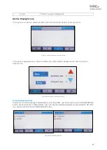
Page 47: ...ing the box back to grey Note Pump ON OFF function is disabled during running of machine Figure 37 Running Pump Choosing the Coolant Setpoint The Coolant setpoint can be set by choosing values using the arrows and changing the increments accordingly By clicking on the increments the increment can be changed from 0 1 to 1 0 and vice versa Running the system The system can be run by pressing the RUN...

Page 48: ...e unit will be shown at the bottom The following information is displayed Information Description Coolant Supply Temperature This is the Supply Temperature from the chiller to the application Return Temperature This is the Return Temperature from the application to the chiller Pressure This is the Supply Pressure to your application from the chiller Temperature setpoint This is the Temperature Set...

Page 49: ...riences an alarm condition the alarm button changes on the home screen to indicate this Figure 42 Home screen with an active alarm Acknowledging Alarms Alarms can be acknowledged individually by selecting them and then pressing the ACKNOWLEDGE button When there are multiple alarms they can be acknowledged together by pressing the SELECT ALL button and then the ACKNOWLEDGE button Figure 43 Acknowle...

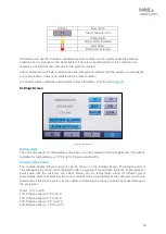
Page 50: ...nu Setting Units The units of measure for temperature and pressure can be selected in the Settings Menu The options available for temperature are C F and for Pressure are Bar Psi Choosing the Coolant The coolant Water Ethylene Glycol can be chosen on the Settings Menu The Ethylene Glycol Percentage can be chosen once the EGW button is pressed This selection limits the temperature set point value t...

Page 51: ...led by default If the customer doesn t enable this alarm then the unit would shut off according to the primary high coolant supply pressure value specified in alarms table If this alarm is enabled the default value is 5 bar for this Figure 47 Coolant Supply Pressure Low temp delta This alarm is to alert the customer if the coolant supply temperature doesn t come within this specified deltaT from b...

Page 52: ...unt of time This alarm is disabled by default If the customer enables this alarm then the default value of delta T is 1 and default time is 30 minutes Figure 49 High Temperature Delta Flow Settings Figure 50 Flow Settings If the optional system feature Flow Control Kit has been chosen along with the unit the Flow Sensor option in Flow settings should be turned ON Flow units can be chosen according...

Page 53: ...53 Low flow alarm can be either switched ON or OFF depending on customer selection Once turned on the value can be changed by clicking on the number ...

Page 54: ...nstallation Requirements Operator Blocked Condenser Clean condenser Refer to Cleaning the Heat Exchanger Operator Coolant level too low Check coolant level and top up if necessary Refer to Adding Coolant Operator Disconnected coolant hoses Connect the coolant hoses Refer to Connecting the Coolant Hoses Operator Dirty coolant filter Clean or replace filter Refer to Replace filter Operator No flow i...

Page 55: ...higher than 20 bar Alarm will reset after pressure drops below 11 5 bar Ambient temperature is high or Thermal load on the system is high or Condenser fan is not running or Condenser fan air flow is blocked Compressor stops running pump and the condenser fan keep running Check if the ambient temperature is too high or above operating limits Check if the load on the system is beyond the specified c...

Page 56: ...ssor operation such as voltage current temperature speed etc If this happens during system stat up unit would not Run If this happens while the system is running then the entire system shuts down Turn off the power switch to the unit off Wait 5 seconds to turn the power switch on again and Run the unit If the problem persists contact LTS customer service Coolant Coolant supply pressure high Red Co...

Page 57: ...s not within certain pre specified temperature delta below the temperature set point within a specified amount of time after starting the unit or changing the set point Hot gas bypass heating loop is not functioning properly or ambient temperature is too low Unit alarms to indicate customer the condition Unit continues running Check if the unit has been sitting in ambient temperature below the spe...

Page 58: ...en This will clear the alarm Now Run the unit If the problem persists contact LTS customer service Coolant Temperature Coolant temperature alarm customer Red Customer method to detect high temperature Coolant return inlet temperature is higher than 50 C Depends on the method customer implements Verify the heat load has not exceeded the rating of the recirculating chiller If the unit is still power...

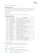
Page 59: ...esent 0 if not present FLW Get flow rate Flow Rate query returns xx xx LPM GPM LVL Coolant level sensor Coolant Level Switch status query returns LOW OK MOD Model Displays the model number PBP Pressure bar psi Set Pressure in bar psi returns bar psi PMP Pump on off Control Power to Pump ON OFF default OFF RDP Get R_CSP Refrigerant Discharge Pressure query returns xx xx bar psi REF Refrigerant type...

Page 60: ...60 PCFLT Returns FLT fault or NO FAULTS FOUND PCFLT C Clears Fault Returns FLT Faults Cleared ...

Page 61: ...s and tools which are lying on each other or lying around are sources of accidents Check all components for soiling and damage Do not use damaged or incorrect components Handle the components with care to avoid damage Assemble components properly Comply with specified screw tightening torques Secure components to prevent them from falling or tipping over Only perform maintenance work using convent...

Page 62: ...The following personal protective gear for all maintenance work must be worn Protective footwear Protective gloves Protective eyewear Maintenance Schedule Follow maintenance task described in table 3 to ensure proper operation of the unit The interval between maintenance are only recommendations and may vary depending on use of the unit and operating environment Table 3 Maintenance Interval Requir...

Page 63: ...Disconnect the unit from mains by pulling the mains plug Secure the unit against being switched on again Verify that the unit is de energized Keep unauthorized persons away from the working area Place the unit on a level surface Verification of Safe State after Maintenance Visually inspect the refrigerant line to make sure there are no leaks Ensure that all screws are securely fastened Make sure t...

Page 64: ...it for Maintenance Coolant hoses disconnected from the unit Refer to Disconnect Hoses Coolant cooled down to the ambient temperature Required Tools and Materials Collection container Hose Note unit holds approximately 5 9 liters of fluid Procedure 1 Make sure Drain Valve is closed 2 Connect hose Place collector container under the drain valve 3 Open Drain Valve Position shown in Fig 4 Close Drain ...

Page 65: ...he heat exchanger can damage the fan and result in a short circuit In this case persons are in danger to get an electric shock Do not clean the heat exchanger with water chemicals NOTE Damage to the fins of the heat exchanger due to improper handling of the unit Damaged fins of the heat exchanger lead to a reduced cooling capacity Take care not to damage the fins of the heat exchanger when cleanin...

Page 66: ... Filter Cartridge 387004497 SP Casters locking 387002803 SP Casters non locking 387002804 SP Compressor fuse 30A 387004338 SP Pressure Switch 387005330 SP Overcurrent Switch 387005152 SP NRC1200 120V Name Part No Pump motor 120V 50 60Hz 387003987 SP Condenser Fan 120V 387003989 SP Tank Cap 387002004 SP Electronic Expansion Valve 387003734 SP Electronic Expansion Valve Coil 387001942 SP Hot gas byp...

Page 67: ...SP Flow meter 387004187 SP Flow adjustment valve 387004180 SP Filter Housing includes filter 387004178 SP Filter Cartridge 387004497 SP Casters locking 387002803 SP Casters non locking 387002804 SP Compressor fuse 30A 387004338 SP Pressure Switch 387005330 SP Overcurrent Switch 387005152 SP NRC5000 Name Part No Pump motor 230V 50 60Hz Option 1 387002071 SP Pump motor 230V 50 60Hz Option 2 38700209...

Page 68: ...er 387004187 SP Flow adjustment valve 387004180 SP Filter Housing includes filter 387004178 SP Filter Cartridge 387004497 SP Casters locking 387002032 SP Casters non locking 387002031 SP Pressure Switch 387005330 SP Overcurrent Switch 387005152 SP ...

Page 69: ...69 Declaration of Conformity ...

Page 70: ... unit Refer to System Maintenance and Service 7 Secure the coolant inlet and coolant outlet connections with protection caps against soiling The unit has now been decommissioned Returning the Unit to Service After Decommissioning Procedure Thoroughly clean the unit Refer to System Maintenance and Service Check that the unit is in operating condition Install the unit and put it into operation Refer...

Page 71: ...s fluorinated greenhouse gas Do not release into water sources or rivers streams Do not release into atmosphere Storage only in approved containers Waste disposal only by qualified contractors Always adhere to manufacturer safety requirements when handling operating supplies Return of the Unit to Laird Declaration of decontamination Before re shipment of the unit a declaration of decontamination m...

Page 72: ...uld call Laird Thermal Systems Customer Service Department at Americas 1 919 597 7300 Europe 46 31 420530 Asia 86 755 2714 1166 www lairdthermal com The Customer will be asked to fill out an RMA form so that RMA can be issued All returns must be securely packed to prevent shipping damage and must be clearly marked with the RMA on the box Consignor shall pay freight charges on all returns ...

Page 73: ...Power Wiring Diagram High Voltage NRC5000 38 Figure 25 Sensor Wiring Low Voltage 39 Figure 26 Plumbing and Refrigeration Diagram 40 Figure 27 Thermal Performance of NRC1200 with Cooling Fluids Water 40 EG W 41 Figure 28 Thermal Performance of NRC2400 with Cooling Fluids Water 40 EG W 41 Figure 29 Pump Performance of NRC1200 with Cooling Fluids Water 40 EG W 42 Figure 30 Pump Performance of NRC2400...

Reviews: