background image

https://www.lairdconnect.com/ 

© Copyright 2022 Laird Connectivity  

All Rights Reserved 

Americas

: +1-800-492-2320 

Europe

: +44-1628-858-940 

Hong Kong

: +852 2762 4823 


Note:


Skip to 

Connect CL4490 to PC

 if you are working with CL4490-1000-232 or CL4490-1000-485  

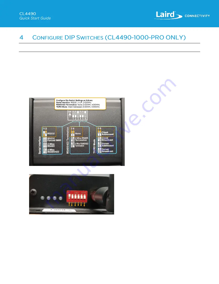
The CL4490-1000-PRO radios have DIP switches on the side of the radio, near the antenna and LEDs as shown below, which 
enable you to select the 

Serial Interface

Termination Settings

, and 

TX/RX Mode

 of the radio. These settings override any 

EEPROM configurations, and so must be configured correctly to operate as expected with the settings that will be configured 
on the radio with the Laird Configuration and Test Utility software. 

In order to configure the radios so they can be connected via the RS232 Interface to a PC, to enable configuration with the 
Laird Configuration and Test Utility software follow these steps: 
 

1.  On 1

st

 radio configure the DIP switches, as per the diagram on the bottom of the CL4490-1000-Pro unit for Serial 

Interface: 

RS232

, Termination: 

None

, TX/RX Mode: 

Client Addressed


Figure 7: DIP Switch Config Diagram 

– Client 


Figure 8: Client DIP Switch Settings 

Summary of Contents for CL4490

Page 1: ...SA 19HS RS485 to USB example ULinx RS485 to USB Model 485USBTB 2W RS485 to RS232 combined with RS232 to USB adapter example B B Electronics Model 485SD9TB PC Operating Windows XP or newer Laird Config...

Page 2: ...ong Kong 852 2762 4823 Figure 1 Extract All 2 Install the extracted files Be sure to run the installation software as administrator right click on Setup exe application and select Run as administrator...

Page 3: ...e files will be installed into Click the button to install Figure 4 Begin installation c Click Continue Figure 5 Continue d Reboot your system to complete the installation Figure 6 Reboot Note Be sure...

Page 4: ...ese settings override any EEPROM configurations and so must be configured correctly to operate as expected with the settings that will be configured on the radio with the Laird Configuration and Test...

Page 5: ...pment that the radio will be interfacing with Note RS232 Forced 9600 is for recovery mode ONLY It should never be used in an application If a baud rate of 9600 is required it should be configured usin...

Page 6: ...1628 858 940 Hong Kong 852 2762 4823 Figure 11 Connected with serial cable c CL4490 1000 485 can be connected using an RS485 to USB adapter or combination RS485 to RS232 RS232 to USB adapter as shown...

Page 7: ...ange of paired server Server radio Green Power LED Red Link LED Figure 14 Client LEDs not paired Server LEDs or client in range of paired server To verify the COM port in the Device Manager follow the...

Page 8: ...a If Select the product from the Product drop down menu b Select the COM Port verified in Device Manager from the drop down menu If none are listed click the Find Ports button c Default baud rate of 5...

Page 9: ...ad Radio Figure 18 Read Successful Note If you receive a message that the read was not successful or Unable to enter command mode verify the Baud setting on PC settings tab You can use AutoBaud mode w...

Page 10: ...er to Client b Set RF Channel 16 by default must be set the same on server c Set System ID 1 by default must be set the same on server d Ensure Auto Destination is enabled e Ensure Broadcast Mode is d...

Page 11: ...follow these steps 1 Return to PC Settings Tab 2 Click Close Port Figure 22 Close port 3 Disconnect from the client and connect to the second radio as per sections 6 7 above 4 Configure the server wit...

Page 12: ...23 Figure 17 Server settings Note The RF Channel and System ID must be set the same on the Server and the Client for them to Pair 5 Click OK when prompted The CU returns Write Successful message when...

Page 13: ...io again to confirm communications and that changes were written correctly to the radio To set the test configurations follow these steps 1 Ensure the power supply is connected to both the client and...

Page 14: ...o the first radio client and make sure that it is at least five feet away from the second unit server 3 With the second unit still connected to the Configuration Utility via the PC click on Range Test...

Page 15: ...To configure a P2MP system follow steps 1 8 to configure the first client and server The Server MUST be configured in Broadcast mode for P2MP systems Then repeat step 7 for as many clients as will be...

Reviews: