https://www.lairdconnect.com/
5
© Copyright 2022 Laird Connectivity
All Rights Reserved
Americas
: +1-800-492-2320
Europe
: +44-1628-858-940
Hong Kong
: +852 2762 4823
2. On the 2
nd
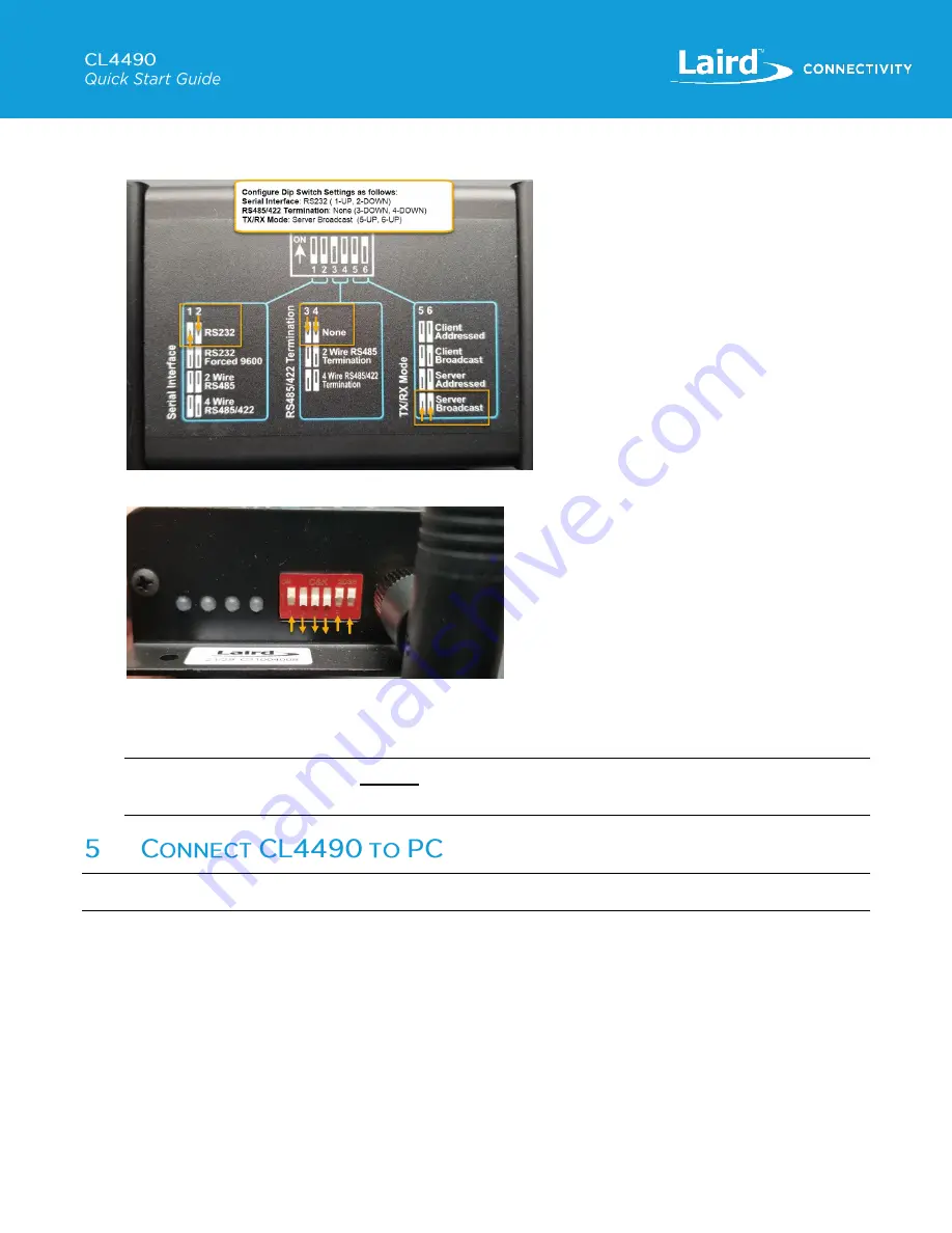
Radio, configure the DIP switches, near the antenna, as per the diagram on the bottom of the CL4490-1000-
Pro unit for Serial Interface:
RS232
, Termination:
None
, TX/RX Mode:
Server/Broadcast
.
Figure 9: DIP Switch Config Diagram
– Server
Figure 10: Server DIP Switch Settings
3. After the radios have been configured with the Configuration Software, the selections for pins 1-2, and 3-4 can be set
as per the requirements for the host equipment that the radio will be interfacing with.
Note:
RS232 Forced 9600 is for
recovery
mode ONLY. It should never be used in an application. If a baud rate of
9600 is required, it should be configured using the Laird Configuration and Test Utility.
Warning
:
Operating the CL4490 Unit without the Antenna attached can damage the radio and void warranty!
To connect the CL4490 to your PC, follow these steps:
1. Attach the antenna to the CL4490.
2. Connect the CL4490 unit to your PC. Depending which variant of the CL4490 is being used, you must connect to your
PC using one of the following setups:
a. CL4490-1000-232/CL4490-1000-PRO can be directly connected to a DB9 serial port on PC using the serial cable
included with the unit.
b. CL4490-1000-232 can be connected using RS232-to-USB serial cable to PC.


