-16-
www.igmtools.com
9. Maintenance
All tools and machines require regular
maintenance, and the bandsaw is no exception.
This section details the general maintenance
and care of your bandsaw. In general, we
recommend that you only use a Teflon-based
lubricant on the bandsaw. While regular oil
attracts dust and dirt, Teflon tends to dry and
has fewer tendencies to accumulate dirt and
sawdust on your machine.
Cleanliness and tire maintenance.
One of the major concerns in regards to the
maintenance of the bandsaw is how clean the
tires are. As the saw cuts, some sawdust lands
on the tire of the lower wheel. As the wheel
rotates, the sawdust becomes compressed on
the tire. This is especially true for woods such
as pine. The compressed sawdust could have
a negative effect, such as vibration, short blade
life and drifting of the blade. A brush contacts
the lower wheel and helps to prevent buildup.
You should inspect the tires regularly to check
that buildup is not happening, especially the
lower wheel. The tires are made of rubber
and wear just like car tires. They wear in the
middle, which causes a concavity in the tire.
The deformation makes it hard to track the
blades, and for this reason it is important to
maintain the original shape of the tire. The best
way to clean the tire surface and maintain the
original shape is to sand it with sandpaper.
The old tire surface often hardens and glazes
over and should be redressed occasionally.
This can be done by sanding the wheel with
100-grit sandpaper. This will take off a little of
the rubber and expose new rubber, which is
desirable. Rotate the wheels by hand with the
blade removed.
Guides
The ceramic side and back guides should be
inspected regularly for cracks and chips. If they
are damaged, they should be replaced as they
could damage your blades and bad guides
will detract from the performance of the
bandsaw. The guides should be cleaned
regularly and any wood gum or dirt removed.
Any commercially available solvent can be
used, and after cleaning they should be
lubricated with Teflon-based lubricant.
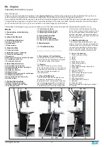
Drive Belt
The drive belt should last for many years
(depending on the usage) but needs to be
inspected regularly for cracks, cuts and general
wear. If damage is found, replace the belt.
Replacing the drive belt
To replace the belts you will have to remove the
lower flywheel.
1. Loosen the motor clamp bolts and move the
motor so that the tension is completely
removed from the drive belt. Remove the blade.
Loosen the two hex nuts that hold the brake
to the bandsaw frame and slide it out of the way
of the disc.
2. Remove the flywheel shaft nut that clamps
the wheel axle (back of the bandsaw).
3. Pull the lower flywheel off the bandsaw. You
may have to use a gear puller to remove the
lower wheel.
4. Replace the drive belt.
5. Refit the lower wheel and re-clamp with the
flywheel shaft nut.
6. Tension the drive belt and tighten the motor
clamping bolts.
Note.
It is better to replace the drive belt early
than to have a breakdown during an
important job.
Note.
Take great care not to damage the
bearings when taking the flywheel off and
reassembling.
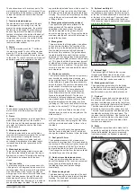
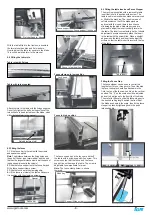
Table Insert.
The table insert (throat plate) is made of
aluminium and is designed to reduce damage
to the blade should they come in contact. If
the blade slot becomes too wide or the insert
becomes damaged by the blade, it should be
replaced. The replacement insert will have to
be fitted to the table hole. The insert is provided
with four jacking screws that can be adjusted so
that the insert is level with the top of the table.
Bearings
All bearings are sealed for life and do not
require any maintenance. If a bearing becomes
faulty, replace it.
Rust
The bandsaw is made from steel and cast
iron. All non-painted surfaces will rust if not
protected. It is recommended that the table be
protected by coating with wax if the machine is
not in constant use. All moving non-painted
surfaces (guides, rack and pinion, etc.) should
be lubricated/protected with a Teflon-based
lubricant.
Blade guide rack and pinion
The top guide when moved vertically tracks the
blade and comes factory-set. Adjustment
is provided should that mechanism become
misaligned. This is a tricky operation and
should only be attempted if an extreme error
has occurred.
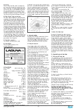
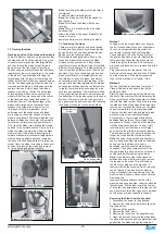
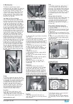
Back guide forward/back adjustment.
1.
Four clamping bolts and two Allen jacking
screws are provided.
2.
Slightly loosen the two clamping bolts A and
tighten the bottom Allen screw B will bring the
guide forward.
3.
Slightly loosen the two clamping bolts C and
tighten the top Allen screw D will bring the guide
back.
4.
Make only very small adjustments. Tighten
the clamping bolts prior to checking the guide
vertical movement.
Note
: The machine comes factory-set, and no
adjustment should be required.
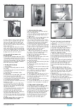
Adjusting the break
Back break adjustor
Front break adjustor
Flywheel not shown for clarity
The back break adjustor moves clockwise to
remove slack in the break pad.
The front break adjustor is rotated clockwise
with an allen key to remove slack in the break
pad.
Clamp bolts C
Allen jacking
screw D
Jack bolt B
Clamping bolts A
Rear Adjusting Knob
Front
Adjusting
Screw
Throat plate jacking screws
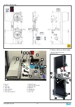
Tire brush
Drive belt
Motor drive pulley
Drive belt adjusting bolt
Flywheel shaft nut

