35
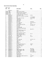
Part List: Conveyor and Motor Assembly
Index Part
No.
No.
Description
Size
Qty
1 .......... 480BS-201 .................... Gear Motor .............................................. 90 VDC .................................... 1
4 .......... 480BS-147 .................... Flat Washer ............................................. 5/16
” ......................................... 4
5 .......... 480BS-205 .................... Socket Head Cap Screw ......................... #10-32x1/2
” .............................. 4
7 .......... 480BS-207 .................... Knob ........................................................ ................................................. 1
8 .......... 480BS-208 .................... Speed Adjustment Label ......................... ................................................. 1
9 .......... 480BS-209 .................... Wiring Guard ........................................... ................................................. 1
10 ........ 480BS-210 .................... Controller ................................................. ................................................. 1
11 ........ 480BS-211 .................... Control Housing Bracket ......................... ................................................. 1
12 ........ 480BS-212 .................... Pan Head Self-Tapping Screw ............... 5/32
”x1/2” ................................. 2
13 ........ 480BS-213 .................... Receptacle, Main Cord ........................... ................................................. 1
14 ........ 480BS-214 .................... Pan Head Machine Screw ...................... #10-32x1/2
” .............................. 1
15 ........ 480BS-215 .................... Washer, Lock-Int. Tooth .......................... #10 ........................................... 1
16 ........ 480BS-216 .................... Hex Nut ................................................... #10-32 ...................................... 1
17 ........ 480BS-217 .................... Screw, Hex Head-Slotted ........................ #10-32x3/8
” .............................. 5
18 ........ 480BS-218 .................... Screw, Phil Pan Head ............................. #6-32x1/2
” ................................ 2
19 ........ 480BS-219 .................... Switch, ON/OFF ...................................... ................................................. 1
20 ........ 480BS-220 .................... Coupler, Shaft ......................................... ................................................. 1
21 ........ 480BS-113 .................... Set Screw ................................................ 1/4-20x1/4
” ............................... 2
22 ........ 480BS-222 .................... Bracket, Base- Controller ........................ ................................................. 1
23 ........ 480BS-223A .................. Cover, Base-Control Housing ................. ................................................. 1
24 ........ 480BS-224 .................... Hex Cap Screw ....................................... 1/4
”-20x3/4”.............................. 4
25 ........ 480BS-225 .................... Washer, Wave......................................... 1/4
” ........................................... 4
26 ........ 480BS-145 .................... Flat Washer ............................................. 1/4
” ........................................... 4
27 ........ 480BS-227 .................... Bracket, Take Up-Slide ........................... ................................................. 2
28 ........ 480BS-154 .................... Bushing, Oilite. ........................................ ................................................. 4
29 ........ 480BS-229 .................... Roller, Driven .......................................... ................................................. 1
30 ........ 480BS-230 .................... Wrench .................................................... ................................................. 2
31 ........ 480BS-231 .................... Hex Nut ................................................... 1/4
”-20 ...................................... 2
32 ........ 480BS-232 .................... Washer, Lock-Int. Tooth .......................... 1/4
” ........................................... 2
33 ........ 480BS-233 .................... Screw, Round Head- Slotted .................. 1/4
”-20x1-3/4” .......................... 2
34 ........ 480BS-234 .................... Bracket, Take Up-Base ........................... ................................................. 2
35 ........ 480BS-167 .................... Lock Washer ........................................... 5/16
” ......................................... 4
36 ........ 480BS-236 .................... Roller, Drive ............................................ ................................................. 1
37 ........ 480BS-237 .................... Bracket, Support-Drive Roller ................. ................................................. 1
38 ........ 480BS-238 .................... Bed, Conveyor ........................................ ................................................. 1
39 ........ 480BS-239 .................... Round Socket Head Cap Screw ............. 5/16
”-18x3/4” ........................... 2
40 ........ 480BS-240 .................... Belt Conveyor, Rubber (Not Shown) ...... ................................................. 1
41 ........ 480BS-241 .................... Flat Washer ............................................. 5/16
” ......................................... 1
42 ........ 480BS-242 .................... Hex Nut ................................................... 5/16
“-24 .................................... 1
43 ........ 480BS-243 .................... Slotted Set Screw ................................... #8-36UNFx5/16
” ...................... 1
44 ........ PLAREVO1216-190 ...... Strain Relief, Gear Motor ........................ 6P-4 ......................................... 1
45 ........ 480BS-245 .................... Hex Nut ................................................... 5/16
”-18 .................................... 2
46 ........ 480BS-246 .................... Receptacle, Signal Cord ......................... ................................................. 1
47 ........ 480BS-247 .................... Hex Cap Screw ....................................... 1/4-20x1/2
” ............................... 8
61 ........ 480BS-1111 .................. Washer, Lock-Int. Tooth .......................... M4 ............................................ 1
62 ........ 480BS-262 .................... Screw ...................................................... M4x0.7x8 ................................. 1
63 ........ 913003-361 ................... Screw ...................................................... M5x0.8x8 ................................. 4
64 ........ 480BS-117 .................... Screw ...................................................... M4x0.7x6 ................................. 4
65 ........ 480BS-265 .................... Snap Bushings ........................................ ................................................. 1
66 ........ PG-13.5 ......................... Strain Relief............................................. PG-13.5 .................................... 1
67 ........ 480BS-267 .................... Junction Box............................................ ................................................. 1
68 ........ 913003-362 ................... Connectors for Junction Boxes (not shown) ............................................. 2
Summary of Contents for SuperMax 19-38 Combo
Page 1: ...19 38 Combo Brush Drum Sander Owner s Manual Lagunatools com SKU 219383...
Page 31: ...31...
Page 34: ...34 34...
Page 36: ...36...
Page 39: ...39...

