


134
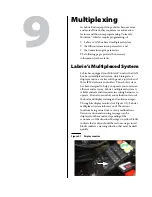
Multiplexing
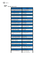
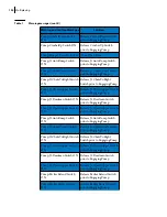
Pump:CrusherDown Switch
ON
Release CrusherDown Switch
prior to Engaging Pump
Pump:CrusherUp Switch ON
Release CrusherUp Switch
prior to Engaging Pump
Pump:Hopper Door Not Close Close Open Door
Pump:J1 AutoDump Switch
ON
Release J1 AutoDump Switch
prior to Engaging Pump
Pump:J1 ChuteToLeft Switch
ON
Release J1 ChuteToLeft Switch
prior to Engaging Pump
Pump:J1 ChuteToRight Switch
ON
Release J1 ChuteToRight
Switch prior to Engaging Pump
Pump:J1 CloseGripper Switch
ON
Release J1 CloseGripper Switch
prior to Engaging Pump
Pump:J1 Deadman Switch ON Release J1 Deadman Switch
prior to Engaging Pump
Pump:J1 OpenGripper Switch
ON
Release J1 OpenGripper Switch
prior to Engaging Pump
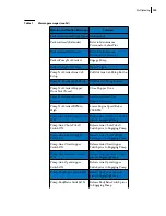
Pump:J2 AutoDump Switch
ON
Release J2 AutoDump Switch
prior to Engaging Pump
Pump:J2 ChuteToLeft Switch
ON
Release J2 ChuteToLeft Switch
prior to Engaging Pump
Pump:J2 ChuteToRight Switch
ON
Release J2 ChuteToRight
Switch prior to Engaging Pump
Pump:J2 CloseGripper Switch
ON
Release J2 CloseGripper Switch
prior to Engaging Pump
Pump:J2 Deadman Switch ON Release J2 Deadman Switch
prior to Engaging Pump
Pump:J2 OpenGripper Switch
ON
Release J2 OpenGripper Switch
prior to Engaging Pump
Pump:Packer Extend Switch
ON
Release Packer Extend Switch
prior to Engaging Pump
Pump:Packer Retract Switch
ON
Release Packer Retract Switch
prior to Engaging Pump
Table 1
Warning messages (cont’d)
Warning and Caution Messages
Solution
Summary of Contents for MINIMAX
Page 1: ...MINIMAX TM MAINTENANCE MANUAL...
Page 2: ......
Page 3: ...MINIMAX MAINTENANCE MANUAL...
Page 8: ...vi Table of Contents Adjusting Arm Speed 164...
Page 30: ...22 Safety Figure 2 17 Drain valve on air tank...
Page 72: ...64 Lubrication Figure 4 10 Lubrication chart Helping Hand arm...
Page 80: ...72 Lubrication...
Page 90: ...82 Hydraulic System Figure 5 8 Oil temp level gauge Figure 5 9 Steel hydraulic tank...
Page 102: ...94 Hydraulic System Figure 5 21 Strainer assembly Strainer...
Page 106: ...98 Hydraulic System Figure 5 25 Detecting cylinder internal leaks 1 2 3 4 5 A A A...
Page 108: ...100 Hydraulic System...
Page 113: ...Electrical System 105 Electrical Schematics Cab Adaptation...
Page 114: ...106 Electrical System Cab Console Controls...
Page 115: ...Electrical System 107 Cab Controller...
Page 116: ...108 Electrical System Chassis...
Page 117: ...Electrical System 109 Body Module rear side...
Page 118: ...110 Electrical System Body Module front side...
Page 119: ...Electrical System 111 Tailgate Lighting...
Page 120: ...112 Electrical System Panic Bars Crusher Panel Tipper Interlocks...
Page 121: ...Electrical System 113 Cameras Switchpack Details Interlocks AUTO 10 SEC INHIBIT AUTO N AUTO ON...
Page 122: ...114 Electrical System...
Page 127: ...Troubleshooting 119 Figure 8 4 Ball end hex wrench metric and SAE...
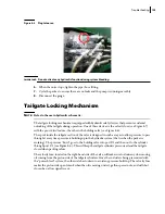
Page 134: ...126 Troubleshooting Figure 8 6 Tailgate locking mechanism...
Page 156: ...148 Multiplexing...
Page 162: ...154 Multiplexing...
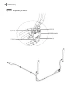
Page 164: ...156 Lifting Arm Figure 10 1 Mounting bolts Figure 10 2 Helping Hand gripper Figure 10 3 Hoses...