8 | MSD Legend Series Operation & Maintenance Manual
INSTALLATION
1.
Locate flat, hard ground (e.g. concrete floor).
2.
Place the shear on the ground so the boom pivot is up.
Use blocking to keep the shear stable and level.
3. Remove the excavator bucket. Follow the
manufacturer’s recommended procedure
Note: Plug hydraulic hoses and lines to prevent
contamination.
SECOND MEMBER INSTALLATION
Note: A second member mount is where the shear
replaces the excavator stick.
1.
Remove the excavator stick. Follow the manufacturer’s
recommended procedure.
2.
Bring the excavator in position, carefully lining up the
boom with the shear boom connection on the mounting
bracket.
Note: it may be necessary to lift the rear of the shear
with a hoist or forklift, to allow the boom to connect to
the bracket.
3. Pin the excavator boom to the boom connection (See
4.
Clear all personnel and instruct the excavator operator
to slowly lift the shear so there will be enough clearance
to pin the excavator cylinder to the cylinder connection.
5.
Extend the arm cylinder rod and connect the cylinder to
the cylinder connection using the cylinder connection
pin.
6.
If you have a rotating shear, remove the transport pin
and place it in its stowed position (see Figure 12).
THIRD MEMBER INSTALLATION
Note: A third member installation is where the shear
replaces the excavator bucket.
1.
Bring the excavator in position, carefully lining up the
stick tip wit the stick connection on the mounting
bracket.
Note: it may be necessary to lift the rear of the shear
with a hoist or forklift, to allow the stick to connect to the
bracket.
2.
Pin the excavator stick to the stick connection.
3. Carefully extend the excavator bucket cylinder to move
the bucket linkage. Position the link into the mounting
bracket linkage connection.
4.
Pin the linkage connection to the shear bracket.
5.
Remove the transport pin and place it in its stowed
position (see Figure 12).
NON-ROTATING INSTALLATION
Care must be taken when unloading the shear. Place the
shear on secure, stable blocking. Ensure the blocking
will not allow the upper jaw move in any way or touch the
ground.
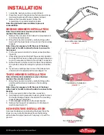
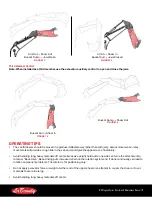
Second Member Installation
Figure 9
Non Rotating Installation
Figure 11
Third Member Installation
Figure 10


