


Page 21
N
EO
T
HERM
Boilers and Water Heaters
REMARQUE
: Lorsqu’une chaudière existante est
supprimée d’un système de ventilation commun, le système
de ventilation commun est susceptible d’être trop grande
pour garantir une aération correcte des appareils restant
connecté à elle. Lors de la dépose d’une chaudière existante,
les étapes suivantes doivent être suivies avec chaque
appareil reste connecté à la système de ventilation commun
mis en opération, alors que les autres appareils connectés
restants à la politique commune de système d’aération ne
sont pas en opération.
1. Joint les ouvertures inutilisées dans le système de
ventilation commun.
2. Inspecter visuellement le système de ventilation à la
taille correcte et espacement horizontal et déterminer il n’y
a pas de blocage ou de restriction, de fuite, de corrosion
et d’autres lacunes que pourrait causer une condition
dangereuse
3. Dans la mesure où cela est pratique, fermer tous les
bâtiments de portes et fenêtres et toutes les portes entre
l’espace dans lequel les appareils connectés restants à la
système de ventilation commun sont situés et d’autres
espaces du bâtiment. Allumer les sécheuses et tout appareil
non connecté au système de ventilation commun. Mettez
sous tension tous les ventilateurs d’échappement d’air, tels
que les hottes de cuisine et salle de bains exhausts, afin
qu’ils fonctionnent à la vitesse maximum. Ne pas faire
fonctionner un ventilateur d’échappement d’été. Fermer
cheminée amortisseurs.
4. Place dans le fonctionnement de l’appareil inspecté.
Suivez les instructions d’éclairage. Réglez le thermostat de
sorte que l’appareil fonctionnera en continu.
5. Test pour les pertes sur les projets d’ouverture de
secours de capot après 5 minutes de fonctionnement du
brûleur principal. Utilisez la flamme d’une allumette ou
une bougie allumée, ou de la fumée d’une cigarette, un
cigare ou une pipe.
6. Après qu’il a été déterminé que chaque appareil reste
connecté au système de ventilation commun correctement
évents lorsque testé comme décrit ci-dessus, le retour
des portes, des fenêtres, ventilateurs d’échappement,
amortisseurs de cheminée et tout autre appareil de
combustion du gaz à leurs conditions d’utilisation
précédente.
7. Tout fonctionnement incorrect du système de
ventilation commun devrait être corrigée de sorte que
l’installation est conforme aux code de gaz combustible
National, ANSI Z223.1/NFPA 54 et/ou CSA B149.1,
Codes d’installation. Lors du redimensionnement de
toute portion de la système de ventilation commun, le
système de ventilation commun doit être redimensionné
à l’approche de la taille minimale, déterminée en utilisant
les tableaux appropriés et des lignes directrices dans le
National Code de gaz combustible, ANSI Z223.1 NFPA 54
et/ou CSA B149.1, Codes d’installation.
3.5 Common Vent Test
NOTE:
This section does not describe a method for
common venting NeoTherm units. It describes what
must be done when a unit is removed from a common
vent system. NeoTherm units require special vent
systems and fans for common vent. Contact the factory
if you have questions about common venting NeoTherm
units.
NOTE: When an existing boiler is removed from a
common venting system, the common venting system is
likely to be too large for proper venting of the appliances
remaining connected to it.
At the time of removal of an existing boiler, the following
steps shall be followed with each appliance remaining
connected to the common venting system placed in
operation, while the other appliances remaining connected
to the common venting system are not in operation.
1. Seal any unused openings in the common venting
system.
2. Visually inspect the venting system for proper size
and horizontal pitch and determine there is no blockage or
restriction, leakage, corrosion and other deficiencies which
could cause an unsafe condition.
3. Insofar as it is practical, close all building doors and
windows and all doors between the space in which the
appliances remaining connected to the common venting
system are located and other spaces of the building. Turn
on clothes dryers and any appliance not connected to the
common venting system. Turn on any exhaust fans, such as
range hoods and bathroom exhausts, so they will operate
at maximum speed. Do not operate a summer exhaust fan.
Close fireplace dampers.
4. Place in operation the appliance being inspected.
Follow the lighting instructions. Adjust the thermostat so
the appliance will operate continuously.
5. Test for spillage at the draft hood relief opening after 5
minutes of main burner operation. Use the flame of a match
or candle, or smoke from a cigarette, cigar or pipe.
6. After it has been determined that each appliance
remaining connected to the common venting system
properly vents when tested as outlined above, return doors,
windows, exhaust fans, fireplace dampers and any other gas
burning appliance to their previous conditions of use.
7. Any improper operation of the common venting system
should be corrected so that the installation conforms to the
National Fuel Gas Code, ANSI Z223.1/NFPA 54 and/or
CSA B149.1, Installation Codes. When resizing any portion
of the common venting system, the common venting
system should be resized to approach the minimum size as
determined using the appropriate tables and guidelines in
the National Fuel Gas Code, ANSI Z223.1 NFPA 54 and/or
CSA B149.1, Installation Codes.
Summary of Contents for NTH
Page 4: ...LAARS Heating Systems...
Page 13: ...Page 9 NEOTHERM Boilers and Water Heaters 38 1 2 98 8 3 4 22 7 1 2 19 64...
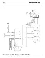
Page 30: ...Page 26 LAARS Heating Systems Figure 21 Hydronic Piping Single Boiler Zoning with Circulators...
Page 86: ...Page 82 LAARS Heating Systems Parts Illustration 1 Jacket Components...
Page 88: ...Page 84 LAARS Heating Systems Parts Illustration 4 Internal Components Sizes 750 850...
Page 90: ...Page 86 LAARS Heating Systems Parts Illustration 6 Gas Train Components Sizes 600 850...
Page 93: ...Page 89 NEOTHERM Boilers and Water Heaters Notes...
Page 94: ...Page 90 LAARS Heating Systems Notes...
Page 95: ...Page 91 NEOTHERM Boilers and Water Heaters Notes...