Page 3
1
The LT Series has been set up at the factory for altitudes
of less than 2,000 ft, but it may be installed at elevations
up to 10,000 ft for use with Natural Gas or Propane. If the
installation is at an altitude of greater than 2,000 ft, then
altitude settings need to be adjusted in the Installer Mode
as describe below.
NOTE: Above 2,000 ft (610 m), the water heater will
de-rate by 2-4% for each 1,000 ft (305 m) of altitude gain.
E
4.12 Gas High Altitude Setting
(no adjustment is needed below 2000 feet)
9:HA
Choose the correct value from the
following four options.
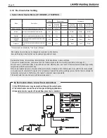
0 - 2
0 ~ 1,999 ft (0
-
609 m)
2
-
5
2,000 ~ 4,999 ft (610
-
1,523 m)
5
-
8
5,000 ~ 7,999 ft (1,524
-
2,438 m)
8
-
10
8,000 ~ 10,000 ft (2,439
-
3,048 m)
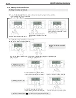
High Altitude settings (2,000 ~ 10,000 ft)
1. With the Power
turned OFF, press the 'Modes button'
for 5 seconds to get into the Installer
Parameters Mode.
2. Turn the dial until ‘10:HA’ appears.
3. Press the dial.
4. Set the high altitude value by turning the dial.
Refer to Table 13 for proper altitude setting.
5. Press the dial again to save the setting.
6. Press the ‘Modes button’
for one second, to Save the number and to go back to initial status.
Table 13. Altitude Settings
10 : HA
6. Wait for your combustion analyzer to stabilize. Then
measure the CO2 for MIN fire. Refer to Table 11 for
acceptable MIN fire combustion readings.
7. If needed, open the gas valve adjustment port by
removing the cap screw with a T15 Star wrench
8. Use the Star wrench to make a minor adjustments;
1/8 of a turn clockwise to increase or 1/8 of a turn
counterclockwise to decrease CO2.
9. It may be necessary to go back and forth between
MAX fire and MIN fire several times (making
adjustments only at MIN fire) before CO
2
levels
are acceptable. Be sure to put the adjustment
port cap screw back into the valve when done.
10. Once the CO2 and manifold pressure
measurements for MIN fire are acceptable per
Table 12, set dip switches 6 and 7 to the OFF
position for nominal fire (normal operation).
Summary of Contents for LT Series
Page 42: ...Page 42 4 20 Wiring Diagram...
Page 43: ...Page 43 4 21 Ladder Diagram...


