background image

Specications

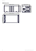
 SB28 dimensions

700 mm / 27.6 in

1300 mm / 51.2 in

55

m

m

 / 

21

.7

 in

130 

 Kara IIi owner's manual (EN) version 2.0

Summary of Contents for Kara IIi

Page 1: ...Kara IIi owner s manual EN ...

Page 2: ... s manual EN version 2 0 Distribution date March 30 2021 2021 L Acoustics All rights reserved No part of this publication may be reproduced or transmitted in any form or by any means without the express written consent of the publisher ...

Page 3: ... Preset description 15 Connectors 16 Rigging system description 17 Kara IIi SB18 IIi system rigging 17 Enclosures 18 Kara IIi 18 SB18 IIi 20 Rigging elements 21 KARAIIi BUMP 21 M BARi 24 KARAIIi RIGBAR 24 KARAIIi TILT 28 KARAIIi FIXBRACKET KARAIIi TILTBRACKET 31 Front screens 34 Mechanical safety 36 Loudspeaker con gurations 39 Line source 39 Line source with low frequency element 40 Line source e...

Page 4: ... KARAIIi TILTBRACKET 76 Stacking Kara IIi on top of SB18 IIi with KARAIIi TILT 81 Exchanging Kara IIi grills 92 Securing a screen 94 Connection to LA ampli ed controllers 97 Cabling schemes 98 Cabling Kara IIi and SB18 IIi 100 Assembly 100 Corrective maintenance 104 Introduction 104 Tools and consumables 104 Kara IIi 105 SB18 IIi 114 Speci cations 121 APPENDIX A Angle settings with KARAIIi TILT 13...

Page 5: ...e familiar with the rigging techniques and safety recommendations outlined in this manual Ensure personnel health and safety During installation and set up personnel must wear protective headgear and footwear at all times Under no circumstances is personnel allowed to climb on a loudspeaker assembly Respect the Working Load Limit WLL of third party equipment L Acoustics is not responsible for any ...

Page 6: ...notice Check www l acoustics com on a regular basis to download the latest document and software updates Long term exposure to extreme conditions may damage the product For more information refer to the Products weather protection document available on the website Read the maintenance section of this document before servicing the product Contact L Acoustics for advanced maintenance Any unauthorize...

Page 7: ...limits and the available acoustical con gurations Mechanical safety p 36 Loudspeaker con gurations p 39 3 Before rigging the system perform mandatory inspections and functional checks 4 To deploy the system follow the step by step rigging instructions and refer to the cabling schemes Rigging procedures p 47 Connection to LA ampli ed controllers p 97 The Corrective maintenance p 104 section contain...

Page 8: ...to bare wire cable This cable needs to be custom made Information about the connection of the enclosures to the LA ampli ed controllers is given in this document Refer to the LA2Xi LA4X LA8 LA12X owner s manual for detailed instructions about the whole cabling scheme including modulation cables and network Rigging elements M BARi Extension bar for rigging frame installation version KARAIIi RIGBAR ...

Page 9: ... control and monitoring of ampli ed controllers Refer to the Soundvision help Refer to the LA Network Manager help Loudspeaker cables 1 1 2 2 1 1 2 2 1 1 2 2 2 5 mm 2 cable 4 x 2 5 mm 2 cable 4 point speakON cable 2 5 mm 2 gauge to bare wire cable This cable needs to be custom made Rigging elements M BARi KARAIIi RIGBAR KARAIIi BUMP KARAIIi SCREEN SB18IIi SCREEN Kara IIi owner s manual EN version ...

Page 10: ...Ii LINK Rigging plates for SB18 IIi SB18IIi ENDLINK End rigging plates for SB18 IIi x2 x2 x2 KARAIIi TILT Rigging elements with angles for Kara IIi above or under SB18 IIi KARAIIi FIXBRACKET Fastening brackets for Kara IIi and SB18 IIi KARAIIi TILTBRACKET Fastening brackets with angles for Kara IIi 10 Kara IIi owner s manual EN version 2 0 ...

Page 11: ...y to one of four settings 110 70 symmetric or 90 asymmetric 35 55 or 55 35 A speci c Kara IIi preset must be used for each directivity setting Within a line source combine Kara IIi with custom directivity settings to improve SPL mapping and throw capability 110 setting preset KARA II 110 55 5 5 Kara IIi owner s manual EN version 2 0 11 ...

Page 12: ...70 setting preset KARA II 70 Set the ns in the 35 position to provide the system with a 2 dB on axis gain 1 kHz compared to the 110 setting 35 3 5 90 settings preset KARA II 90 35 5 5 55 3 5 12 Kara IIi owner s manual EN version 2 0 ...

Page 13: ...on angle diagrams of one Kara IIi in the horizontal plane for all ns settings using lines of equal sound pressure at 3 dB 6 dB 12 dB 100 1 000 10 000 Frequency Hz 180 160 140 120 100 80 60 40 20 0 20 40 60 80 100 120 140 160 180 Angle 110 ns setting Kara IIi owner s manual EN version 2 0 13 ...

Page 14: ...quency Hz 180 160 140 120 100 80 60 40 20 0 20 40 60 80 100 120 140 160 180 Angle 70 ns setting 100 1 000 10 000 Frequency Hz 180 160 140 120 100 80 60 40 20 0 20 40 60 80 100 120 140 160 180 Angle 90 ns setting 14 Kara IIi owner s manual EN version 2 0 ...

Page 15: ...N LF OUT 3 LF ON HF OUT 4 HF IN B 0 dB 0 ms ON KS28_60 SB28_60 KS21_60 KS21_100 SB18_60 SB18_100 outputs channels routing gain delay polarity mute OUT 1 SB IN A 0 dB 0 ms ON OUT 2 SB IN A 0 dB 0 ms ON OUT 3 SB IN A 0 dB 0 ms ON OUT 4 SB IN A 0 dB 0 ms ON KS28_60_C KS28_60_Cx SB28_60_C SB28_60_Cx KS21_60_C KS21_100_C KS21_60_Cx KS21_100_Cx SB18_60_C SB18_100_C SB18_60_Cx SB18_100_Cx loudspeaker ele...

Page 16: ...y KARA IIi Weight 21 kg 47 lb LF HF LF HF Znom 8 Ω Kara IIi 2 4 point terminal block with push in connection Internal pinout for L Acoustics 2 way active enclosures terminal block points 1 1 2 2 Transducer connectors LF LF HF HF SB18 IIi 1 4 point terminal block with push in connection Internal pinout for L Acoustics subwoofers terminal block points IN IN Transducer connectors LF LF 16 Kara IIi ow...

Page 17: ...re assembled together with rigging plates and rigging accessories suited for installation Like the Kara II SB18 system the enclosures can be deployed in own or stacked arrays Multiple rigging kits are available depending on the desired con guration refer to Rigging plates p 10 Do not combine Karai SB18i elements and Kara IIi SB18 IIi elements within the same array The two systems are not mechanica...

Page 18: ...tes KARAIIi ENDLINK With KARAIIi LINK the inter element angle between two Kara IIi can be set to 0 1 2 3 4 5 7 5 or 10 0 1 2 4 3 5 7 5 10 A B right hand side KARAIIi LINK Kara IIi features seven M6 inserts on each side Five M6 inserts for rigging Two M6 inserts for securing a screen Refer to Securing a screen p 94 18 Kara IIi owner s manual EN version 2 0 ...

Page 19: ...aks Do not remove the placeholder screws from the bottom rear inserts A or B that are not used Kara IIi rear linking points rigging accessory inter element angle used inserts 0 2 4 7 5 A KARAIIi LINK connecting from an enclosure below 1 3 5 10 B KARAIIi RIGBAR last enclosure with pullback B KARAIIi TILTBRACKET all angles A none last enclosure in the array A Rigging screws Only use the rigging scre...

Page 20: ...es ten M6 inserts on each side Six M6 inserts for rigging Four M6 inserts for securing a screen in standard or cardioid con gurations Refer to Securing a screen p 94 The inserts are tted with placeholder screws Rigging screws Only use the rigging screws provided by L Acoustics Do not use the placeholder screws for rigging Always put the placeholder screws back in place to avoid leaks 20 Kara IIi o...

Page 21: ...BUMP KARAIIi BUMP is a rigging frame for ying arrays of Kara IIi or SB18 IIi KARAIIi BUMP can be used as the main lifting accessory for ying vertical arrays of Kara IIi and SB18 IIi with one or two lifting points Kara IIi owner s manual EN version 2 0 21 ...

Page 22: ...is secured to the array with four M6x18 screws and M6 nuts provided With KARAIIi LINK the splay angle with Kara IIi can be set to 5 4 3 2 1 0 2 5 or 5 T30 10 mm 5 N m T30 10 mm 5 N m 5 4 3 1 2 0 2 5 5 22 Kara IIi owner s manual EN version 2 0 ...

Page 23: ...anel They are labeled as follows angle in Soundvision splay angle 5 0 7 5 2 5 10 5 It is recommended to set a 0 splay angle 5 in Soundvision between the rst Kara IIi and KARAIIi BUMP By doing this the Kara IIi axis is parallel to KARAIIi BUMP Nine pickup points are available on the central bar for site angle adjustment They are compatible with Ø19 mm shackles WLL 3 25 t two provided Four holes are...

Page 24: ...each A or B rigging axes front extension in position B M BARi is secured to the rigging frame with two M8 bolts nuts and safety pins 13 mm Seventeen 17 pickup points are available They are compatible with Ø19 mm shackles WLL 3 25 t two provided 1 2 3 4 5 6 7 8 9 10 11 12 13 14 15 16 0 KARAIIi RIGBAR KARAIIi RIGBAR is a rigging bar for pullback con gurations of Kara IIi or SB18 IIi arrays 24 Kara I...

Page 25: ...main lifting accessory With KARAIIi RIGBAR as the main lifting accessory KARAIIi ENDLINK or SB18IIi ENDLINK is required on the top enclosure Risk of collision between shackle and rigging frame When using KARAIIi BUMP as the main lifting accessory for a pullback con guration always secure M BARi on KARAIIi BUMP and use the rear pickup point N 16 Kara IIi owner s manual EN version 2 0 25 ...

Page 26: ...ing system description When used at the top of the array as the main lifting accessory KARAIIi RIGBAR can be secured at the front for an initial positive site angle 26 Kara IIi owner s manual EN version 2 0 ...

Page 27: ...ng Load Limit of 250 kg 550 lb It can support an array of up to 11 Kara IIi or 5 SB18 IIi For an hybrid array check the total weight of the array in Soundvision For more information refer to the CLAMP250 owner s manual When using KARAIIi RIGBAR as the main lifting accessory always implement a secondary safety using available holes One pickup point pickup point safety points Two pickup points safet...

Page 28: ...B18 IIi When stacking Kara IIi on SB18 IIi with KARAIIi TILT Kara IIi must be turned upside down logo on the left hand side Otherwise it is not possible to secure Kara IIi to KARAIIi TILT For aesthetic purposes the front grills can be removed and exchanged when the enclosures are assembled Refer to Exchanging Kara IIi grills p 92 28 Kara IIi owner s manual EN version 2 0 ...

Page 29: ...on KARAIIi TILT in Soundvision enclosures aligned at the front inter element angles from 5 to 15 in 2 5 steps When KARAIIi TILT is secured in standard orientation to a reversed SB18 IIi in a cardioid con guration the SB18 IIi grill cannot be removed Kara IIi owner s manual EN version 2 0 29 ...

Page 30: ...ersed orientation the SB18 IIi grill cannot be removed and SB18IIi SCREEN cannot be secured on the enclosure Geometric delay with reversed KARAIIi TILT In an SB18 IIi Kara IIi array where KARAIIi TILT is reversed add 1 ms geometric delay to Kara IIi For more details about angle settings with KARAIIi TILT refer to APPENDIX A Angle settings with KARAIIi TILT p 137 30 Kara IIi owner s manual EN versi...

Page 31: ...y and to anchor it to the ground KARAIIi TILTBRACKET is a set of four fastening brackets with site angle adjustment for a stack of up to three Kara IIi The enclosure is secured to KARAIIi TILTBRACKET using the round hole The site angle adjustment bracket can be secured at the front or at the rear of the enclosure The site angle can be set between 5 and 15 with the angle bracket at the rear or betw...

Page 32: ... the front the grills cannot be removed and KARAIIi SCREEN cannot be secured on the enclosure The grills on the rst enclosure can be exchanged before rigging Refer to Exchanging Kara IIi grills p 92 5 2 5 0 2 5 5 7 5 10 12 5 15 5 7 5 10 12 5 15 17 5 20 22 5 25 32 Kara IIi owner s manual EN version 2 0 ...

Page 33: ...e turned upside down logo on the left hand side Otherwise it is not possible to mount additional Kara IIi under the rst one and the site angle is not accurate For aesthetic purposes the front grills can be removed and exchanged when the enclosures are assembled Refer to Exchanging Kara IIi grills p 92 KARAIIi FIXBRACKET and KARAIIi TILTBRACKET must be secured to the supporting xture with four M10 ...

Page 34: ...e acoustically transparent front screens for Kara IIi and SB18 IIi The screens are secured on top of the rigging plates with four M6 35 Torx screws which replace the grill screws The grill screws can be removed through the rigging plates 34 Kara IIi owner s manual EN version 2 0 ...

Page 35: ... to hold the grill in place when securing the screen on the enclosure SB18IIi SCREEN can be secured to the back of SB18 IIi when used in cardioid con guration The cable s can be passed through a cutout on the screen side Kara IIi owner s manual EN version 2 0 35 ...

Page 36: ...afety factor can be compliant with the 2006 42 EC Machinery Directive when the other deployment parameters provide the best mechanical conditions For mixed arrays refer to your Soundvision model Kara IIi con guration rigging accessory safe limit maximum limit Flown KARAIIi BUMP M BARi optional rigging plates 12 24 KARAIIi BUMP M BARi KARAIIi RIGBAR rigging plates 12 Flown with pullback KARAIIi RIG...

Page 37: ...m pullback angle If a pullback accessory is available the pullback angle must not exceed a 90 negative site angle Mechanical modeling with Soundvision The working load applied to each linking point along with the corresponding safety factor will depend on numerous variables linked to the composition of the array type and number of enclosures splay angles and the implementation of the ying or stack...

Page 38: ...n usual environmental conditions A higher safety factor is recommended with factors such as extreme high or low temperatures strong wind prolonged exposition to salt water etc Always consult a rigging specialist to adopt safety practices adapted to such a situation 38 Kara IIi owner s manual EN version 2 0 ...

Page 39: ...110 presets deliver a reference frequency response in long throw applications Each preset is dedicated to a horizontal directivity setting see Adjustable ns p 11 The Kara IIi enclosure is driven by the LA2Xi LA4X LA8 LA12X ampli ed controllers Reduced maximum SPL or drive capacity with LA2Xi refer to the LA2Xi owner s manual Enclosure Kara IIi Preset KARA II 70 KARA II 90 KARA II 110 Frequency ran...

Page 40: ...S21i array The xxxx_60 or xxxx_100 presets provide the subwoofers with an upper frequency limit at 60 Hz in separated con guration or 100 Hz in closely coupled con guration for an optimal frequency coupling with the Kara IIi line source Ampli ed controllers compatibility LA2Xi LA4X LA8 LA12X Kara IIi SB18 IIi KS21i SB28 KS28 Reduced maximum SPL or drive capacity with LA2Xi refer to the LA2Xi owner...

Page 41: ... Cardioid con gurations technical bulletin Delay values Do not forget to add the pre alignment and geometric delays depending on the con guration Geometric delay with reversed KARAIIi TILT In an SB18 IIi Kara IIi array where KARAIIi TILT is reversed add 1 ms geometric delay to Kara IIi Pre alignment delays presets pre alignment delay values and polarity settings KARA II SB18_100 Kara II 0 ms SB18 ...

Page 42: ...ofer enclosures side by side If not possible the maximum distance between two adjacent acoustic centers must be 2 8 m if the upper frequency limit of the subwoofer system is at 60 Hz Use xxxx_xx_C or xxxx_xx_Cx on a reversed subwoofer in a cardioid con guration The cardioid con guration consists in reversing 1 element in an array of 4 subwoofers Refer to the subwoofer owner s manual and to the Car...

Page 43: ... presets pre alignment delay values and polarity settings KARA II SB18_60 Kara II 2 5 ms SB18 0 ms KARA II SB18_60_C Kara II 8 ms SB18 0 ms KARA II SB18_60_Cx Kara II 6 5 ms SB18 0 ms KARA II KS21_60 Kara II 0 5 ms KS21 0 ms KARA II KS21_60_C Kara II 6 ms KS21 0 ms KARA II KS21_60_Cx Kara II 5 5 ms KS21 0 ms Kara IIi owner s manual EN version 2 0 43 ...

Page 44: ...e 10 dB 25 Hz 20 kHz Grouping subwoofers Place the subwoofer enclosures side by side If not possible the maximum distance between two adjacent acoustic centers must be 2 8 m if the upper frequency limit of the subwoofer system is at 60 Hz Use xxxx_xx_C or xxxx_xx_Cx on a reversed subwoofer in a cardioid con guration The cardioid con guration consists in reversing 1 element in an array of 4 subwoof...

Page 45: ...ms KARA II SB18_100 SB28_60_Cx Kara II 5 5 ms SB18 5 5 ms SB28 0 ms KARA II SB18_100 KS28_60 Kara II 0 ms SB18 0 ms KS28 5 5 ms KARA II SB18_100 KS28_60_C Kara II 0 ms SB18 0 ms KS28 0 ms KARA II SB18_100 KS28_60_Cx Kara II 5 5 ms SB18 5 5 ms KS28 0 ms KARA II KS21_100 SB28_60 Kara II 0 ms KS21 0 5 ms SB28 5 5 ms KARA II KS21_100 SB28_60_C Kara II 0 ms KS21 0 5 ms SB28 0 ms KARA II KS21_100 SB28_6...

Page 46: ...y response for short throw applications and a high pass lter at 100 Hz The KARA II_FI preset is optimized for a 110 ns setting see Adjustable ns p 11 The Kara IIi enclosure is driven by the LA2Xi LA4X LA8 LA12X ampli ed controllers Reduced maximum SPL or drive capacity with LA2Xi refer to the LA2Xi owner s manual Enclosure Kara IIi Preset KARA II_FI Frequency range 10 dB 85 Hz 20 kHz 46 Kara IIi o...

Page 47: ...visual cues to differentiate them At the top the bottom hole on the linking section is positioned towards the rear of the enclosure At the bottom the shape of the rigging plate is parallel to the edge of the enclosure and the holes and inserts are aligned For other Kara IIi rigging plates front KARAIIi LINK rigging plates KARAIIi ENDLINK the left and right plates are identical For SB18IIi LINK and...

Page 48: ...e in the array A Tightening screws Do not fully tighten the screws unless instructed to do so After securing an enclosure to another enclosure tighten all the screws on the supporting enclosure Apply a torque of 5 N m Stacking enclosures When stacking two enclosures the top enclosure must be slightly lifted to align the inserts with the rigging plate holes Use an accessory like a wedge or a lever ...

Page 49: ...able References are given for FACOM products in this table Other manufacturers can be used Name Reference Distributor Set of 6 point 1 4 sockets RL NANO1 R 360NANO FACOM electric screwdriver with torque selector Torque screwdriver 2 10 N m A 404 FACOM 10 mm wrench 13 mm wrench Kara IIi owner s manual EN version 2 0 49 ...

Page 50: ...x2 x2 x2 KARAIIi LINK Rigging plates for Kara IIi KARAIIi ENDLINK End rigging plates for Kara IIi SB18IIi LINK Rigging plates for SB18 IIi x2 KARAIIi TILT Rigging elements with angles for Kara IIi above or under SB18 IIi Risk of falling objects Verify that no unattached items remain on the product or assembly Secondary safety Use available holes on the rigging accessories to implement a secondary ...

Page 51: ...r screws A B A B Kara IIi rear linking points rigging accessory inter element angle used inserts 0 2 4 7 5 A KARAIIi LINK connecting from an enclosure below 1 3 5 10 B KARAIIi RIGBAR last enclosure with pullback B KARAIIi TILTBRACKET all angles A none last enclosure in the array A b Secure KARAIIi LINK on the enclosures Do not secure the bottom rigging screws except on the last enclosure of the ar...

Page 52: ...t is recommended to set a 0 splay angle 5 in Soundvision between the rst Kara IIi and KARAIIi BUMP By doing this the Kara IIi axis is parallel to KARAIIi BUMP Tighten the screws Apply a torque of 5 N m T30 10 mm 5 N m 5 4 3 1 2 0 2 5 5 3 Select the pickup point s and raise the array until the bottom of the enclosure is accessible FRONT A B A B 1 2 4 3 5 6 7 8 9 KARAIIi BUMP pickup points 1 2 3 4 5...

Page 53: ...re the second Kara IIi under the array a Lift Kara IIi and link the enclosures at the front with rigging screws Do not fully tighten the screws b Link the enclosures at the rear with the rigging screws Select the holes and inserts depending on the inter element angle 0 1 2 4 3 5 7 5 10 A B Kara IIi owner s manual EN version 2 0 53 ...

Page 54: ...t step 4 p 53 until the array is completed 6 Tighten all the screws on the last enclosure Apply a torque of 5 N m 7 Check that all the screws are secured and tightened and raise the array What to do next Adding a pullback with KARAIIi RIGBAR p 65 Securing a screen p 94 54 Kara IIi owner s manual EN version 2 0 ...

Page 55: ... reversed orientation the SB18 IIi grill cannot be removed and SB18IIi SCREEN cannot be secured on the enclosure Procedure 1 Prepare all SB18 IIi needed for the array a Remove the placeholder screws b Secure SB18IIi LINK on the enclosures Do not secure the bottom screws Kara IIi owner s manual EN version 2 0 55 ...

Page 56: ...ns Tighten all the screws on KARAIIi BUMP Apply a torque of 5 N m T30 10 mm 5 N m 3 Select the pickup point and raise the array FRONT A B A B 1 2 4 3 5 6 7 8 9 KARAIIi BUMP pickup points 1 2 3 4 5 6 7 8 9 10 11 12 13 14 15 16 0 M BARi pickup points 4 Secure a second SB18 IIi under the array a Place SB18 IIi equipped with SB18IIi LINK under the array 56 Kara IIi owner s manual EN version 2 0 ...

Page 57: ...er the array until the enclosures can be assembled The rigging plates of the bottom enclosure overlap the rigging plates of the top enclosure c Link the enclosures with rigging screws Kara IIi owner s manual EN version 2 0 57 ...

Page 58: ...c leaks Do not remove the placeholder screws from the bottom rear inserts A or B that are not used Remove the relevant placeholder screws A B A B Kara IIi rear linking points rigging accessory inter element angle used inserts 0 2 4 7 5 A KARAIIi LINK connecting from an enclosure below 1 3 5 10 B KARAIIi RIGBAR last enclosure with pullback B KARAIIi TILTBRACKET all angles A none last enclosure in t...

Page 59: ...e settings with KARAIIi TILT p 137 This step requires three operators Hold the enclosure at the bottom until the rigging plates are secured 7 Secure the Kara IIi KARAIIi TILT assembly under the array a Lift the assembly and secure KARAIIi TILT to SB18 IIi with rigging screws Select the holes on KARAIIi TILT depending on the inter element angle Refer to APPENDIX A Angle settings with KARAIIi TILT p...

Page 60: ...m the Kara IIi rigging plates 8 To add additional Kara IIi under the array follow the procedure in Kara IIi array assembly p 51 9 Check that all screws are present and tightened and raise the array What to do next Adding a pullback with KARAIIi RIGBAR p 65 Securing a screen p 94 60 Kara IIi owner s manual EN version 2 0 ...

Page 61: ...Torx bit Min number of operators 3 Rigging plates x2 x2 x2 x2 KARAIIi LINK Rigging plates for Kara IIi KARAIIi ENDLINK End rigging plates for Kara IIi SB18IIi LINK Rigging plates for SB18 IIi SB18IIi ENDLINK End rigging plates for SB18 IIi Risk of falling objects Verify that no unattached items remain on the product or assembly Secondary safety Use available holes on the rigging accessories to imp...

Page 62: ... A B Kara IIi rear linking points rigging accessory inter element angle used inserts 0 2 4 7 5 A KARAIIi LINK connecting from an enclosure below 1 3 5 10 B KARAIIi RIGBAR last enclosure with pullback B KARAIIi TILTBRACKET all angles A none last enclosure in the array A On SB18 IIi 62 Kara IIi owner s manual EN version 2 0 ...

Page 63: ...ging procedures b Secure end rigging plates on the enclosure KARAIIi ENDLINK on Kara IIi SB18IIi ENDLINK on SB18 IIi Do not secure the rear top screws on each side Kara IIi owner s manual EN version 2 0 63 ...

Page 64: ...the array Maximum limit with CLAMP250 CLAMP250 has a WLL Working Load Limit of 250 kg 550 lb It can support an array of up to 11 Kara IIi or 5 SB18 IIi For an hybrid array check the total weight of the array in Soundvision For more information refer to the CLAMP250 owner s manual 4 To complete the array follow the procedure in Flying an array with KARAIIi BUMP p 50 What to do next Adding a pullbac...

Page 65: ...x bit Min number of operators 1 KARAIIi RIGBAR uses rear linking points B on Kara IIi A B A B Assembly Prerequisite Prepare the array as described in Flying an array with KARAIIi BUMP p 50 or Flying an array with KARAIIi RIGBAR p 61 Procedure 1 Raise the array until the bottom enclosure is accessible 2 Remove the bottom screw from the rear rigging plates on each side Kara IIi owner s manual EN ver...

Page 66: ...3 Secure KARAIIi RIGBAR at the rear of the enclosure with M6 40 Torx screws Apply a torque of 5 N m 5 N m 4 Secure a shackle to KARAIIi RIGBAR and lift it with an additional motor 66 Kara IIi owner s manual EN version 2 0 ...

Page 67: ...d rigging plates for Kara IIi Fasteners for ceiling mounting Select screw length and anchors applicable to the ceiling properties Model the array in Soundvision and check the loads on rigging in the Mechanics view Mounting KARAIIi TILTBRACKET to the ceiling When mounting Kara IIi to the ceiling with KARAIIi TILTBRACKET Kara IIi must be turned upside down logo on the left hand side Otherwise it is ...

Page 68: ...rs for ceiling mounting Select screw length and anchors applicable to the ceiling properties Model the array in Soundvision and check the loads on rigging in the Mechanics view 778 mm 30 6 in 321 mm 12 6 in Ø 12 mm 0 5 in 2 Prepare a Kara IIi a Risk of acoustic leaks Do not remove the placeholder screws from the bottom rear inserts A or B that are not used Remove the relevant placeholder screws At...

Page 69: ...Ii upside down and secure it to KARAIIi TILTBRACKET with rigging screws a Secure the enclosure to the round hole on the short bracket Do not fully tighten the screws b Secure the enclosure to the long bracket at the chosen angle 5 2 5 0 2 5 5 7 5 10 12 5 15 5 7 5 10 12 5 15 17 5 20 22 5 25 angles at the rear angles at the front Kara IIi owner s manual EN version 2 0 69 ...

Page 70: ...points rigging accessory inter element angle used inserts 0 2 4 7 5 A KARAIIi LINK connecting from an enclosure below 1 3 5 10 B KARAIIi RIGBAR last enclosure with pullback B KARAIIi TILTBRACKET all angles A none last enclosure in the array A b Secure the rigging plates on the enclosure KARAIIi LINK on the second to last enclosure or KARAIIi ENDLINK on the last enclosure Do not secure the bottom s...

Page 71: ...ional enclosure under the array a Turn the next Kara IIi upside down and link the enclosures at the front with rigging screws Do not fully tighten the screws b Link the enclosures at the rear with rigging screws Select the holes and inserts depending on the inter element angle 0 1 2 4 3 5 7 5 10 A B Kara IIi owner s manual EN version 2 0 71 ...

Page 72: ...the last enclosure 7 Tighten all the screws on the last enclosure 5 N m 8 Check that all the screws are secured and tightened What to do next Exchange the Kara IIi grills so that the logo is positionned on the right hand side Exchanging Kara IIi grills p 92 or secure a screen Securing a screen p 94 72 Kara IIi owner s manual EN version 2 0 ...

Page 73: ...rators 3 Rigging plates x2 x2 x2 x2 KARAIIi FIXBRACKET Fastening brackets for Kara IIi and SB18 IIi KARAIIi LINK Rigging plates for Kara IIi KARAIIi ENDLINK End rigging plates for Kara IIi SB18IIi ENDLINK End rigging plates for SB18 IIi x2 KARAIIi TILT Rigging elements with angles for Kara IIi above or under SB18 IIi Fasteners for ceiling mounting Select screw length and anchors applicable to the ...

Page 74: ...or ceiling mounting Select screw length and anchors applicable to the ceiling properties Model the array in Soundvision and check the loads on rigging in the Mechanics view 778 mm 30 6 in 661 mm 26 in Ø 12 mm 0 5 in 2 Prepare an SB18 IIi a Remove the placeholder screws 74 Kara IIi owner s manual EN version 2 0 ...

Page 75: ...B18 IIi and secure it to the slotted holes on KARAIIi FIXBRACKET with rigging screws Apply a 5 N m torque 5 N m 4 Remove the bottom rigging screws from SB18 IIi 5 Secure up to two Kara IIi under the array with KARAIIi TILT Refer to SB18 IIi Kara IIi array assembly p 55 6 Check that all the screws are secured and tightened What to do next Securing a screen p 94 Kara IIi owner s manual EN version 2 ...

Page 76: ... Rigging plates x2 x2 x2 KARAIIi TILTBRACKET Fastening brackets with angles for Kara IIi KARAIIi LINK Rigging plates for Kara IIi KARAIIi ENDLINK End rigging plates for Kara IIi When KARAIIi TILTBRACKET is secured to Kara IIi with the angle bracket at the front the grills cannot be removed and KARAIIi SCREEN cannot be secured on the enclosure The grills on the rst enclosure can be exchanged before...

Page 77: ...Risk of acoustic leaks Do not remove the placeholder screws from the bottom rear inserts A or B that are not used Remove the relevant placeholder screws At the bottom rear remove placeholder screws A A B A B b Secure KARAIIi LINK on the enclosure For an array of one enclosure secure KARAIIi ENDLINK instead Do not secure the bottom screws Kara IIi owner s manual EN version 2 0 77 ...

Page 78: ...ully tighten the screws b Secure the enclosure to the long bracket at the chosen angle 5 2 5 0 2 5 5 7 5 10 12 5 15 5 7 5 10 12 5 15 17 5 20 22 5 25 angles at the rear angles at the front 4 Prepare additional Kara IIi a Risk of acoustic leaks Do not remove the placeholder screws from the bottom rear inserts A or B that are not used Remove the relevant placeholder screws A B A B 78 Kara IIi owner s...

Page 79: ...sure On the last enclosure of the array secure KARAIIi ENDLINK instead Do not secure the bottom screws Risk of crushing injury Keep ngers away from underneath the enclosure 5 Secure the next Kara IIi on top of the array a Link the enclosures at the front with rigging screws Adjusting the gap between stacked enclosures Place a wedge or a lever between the two enclosures to align the rigging with th...

Page 80: ...3 5 7 5 10 A B c Tighten all the screws on the supporting enclosure Apply a torque of 5 N m 5 N m 6 Repeat step 5 p 79 until the array is complete 7 Tighten the screws on the last enclosure Apply a torque of 5 N m 8 Check that all the screws are secured and tightened What to do next Securing a screen p 94 80 Kara IIi owner s manual EN version 2 0 ...

Page 81: ...nd anchors Tools torque screwdriver T30 Torx bit Min number of operators 2 Rigging plates x2 x2 x2 x2 KARAIIi FIXBRACKET Fastening brackets for Kara IIi and SB18 IIi KARAIIi LINK Rigging plates for Kara IIi KARAIIi ENDLINK End rigging plates for Kara IIi SB18IIi LINK Rigging plates for SB18 IIi x2 x2 SB18IIi ENDLINK End rigging plates for SB18 IIi KARAIIi TILT Rigging elements with angles for Kara...

Page 82: ... possible to secure Kara IIi to KARAIIi TILT For aesthetic purposes the front grills can be removed and exchanged when the enclosures are assembled Refer to Exchanging Kara IIi grills p 92 When KARAIIi TILT is secured to SB18 IIi in reversed orientation the SB18 IIi grill cannot be removed and SB18IIi SCREEN cannot be secured on the enclosure 82 Kara IIi owner s manual EN version 2 0 ...

Page 83: ...sembly Procedure 1 Secure KARAIIi FIXBRACKET to the ground using M10 screws 778 mm 30 6 in 661 mm 26 in Ø 12 mm 0 5 in 2 Prepare up to three SB18 IIi a Remove the placeholder screws Kara IIi owner s manual EN version 2 0 83 ...

Page 84: ...On the last enclosure of the array secure SB18IIi ENDLINK instead Risk of crushing injury Keep ngers away from underneath the enclosure 3 Secure SB18 IIi to the slotted holes on KARAIIi FIXBRACKET Tighten the bottom screws Apply a 5 N m torque 5 N m 84 Kara IIi owner s manual EN version 2 0 ...

Page 85: ...ng the gap between stacked enclosures Place a wedge or a lever between the two enclosures to align the rigging with the inserts Be careful not to scratch the paint The last SB18 IIi must be equipped with SB18IIi ENDLINK 5 Remove the top rigging screws from the last SB18 IIi 6 Tighten all the screws on the array Apply a torque of 5 N m Kara IIi owner s manual EN version 2 0 85 ...

Page 86: ...aks Do not remove the placeholder screws from the bottom rear inserts A or B that are not used Remove the relevant placeholder screws A B A B Kara IIi rear linking points rigging accessory inter element angle used inserts 0 2 4 7 5 A KARAIIi LINK connecting from an enclosure below 1 3 5 10 B KARAIIi RIGBAR last enclosure with pullback B KARAIIi TILTBRACKET all angles A none last enclosure in the a...

Page 87: ...nd secure it on top of the array a Secure Kara IIi to KARAIIi TILT with rigging screws Select the holes on KARAIIi TILT depending on the inter element angle Refer to APPENDIX A Angle settings with KARAIIi TILT p 137 b Tighten all the screws on KARAIIi TILT Apply a torque of 5 N m 5 N m Kara IIi owner s manual EN version 2 0 87 ...

Page 88: ...erts A or B that are not used Remove the relevant placeholder screws A B A B Kara IIi rear linking points rigging accessory inter element angle used inserts 0 2 4 7 5 A KARAIIi LINK connecting from an enclosure below 1 3 5 10 B KARAIIi RIGBAR last enclosure with pullback B KARAIIi TILTBRACKET all angles A none last enclosure in the array A 88 Kara IIi owner s manual EN version 2 0 ...

Page 89: ...derneath the enclosure 11 Secure each additional Kara IIi upside down on top of the array a Adjusting the gap between stacked enclosures Place a wedge or a lever between the two enclosures to align the rigging with the inserts Be careful not to scratch the paint Link the enclosures at the front with rigging screws Do not fully tighten the screws Kara IIi owner s manual EN version 2 0 89 ...

Page 90: ...rews Select the holes and inserts depending on the inter element angle 0 1 2 4 3 5 7 5 10 A B c Tighten all the screws on the supporting enclosure Apply a torque of 5 N m 5 N m 12 Repeat step 11 p 89 until the array is complete 90 Kara IIi owner s manual EN version 2 0 ...

Page 91: ...e of 5 N m 5 N m 14 Check that all screws are secured and tightened What to do next Exchange the Kara IIi grills so that the logo is positioned on the right hand side Exchanging Kara IIi grills p 92 or secure a screen Securing a screen p 94 Kara IIi owner s manual EN version 2 0 91 ...

Page 92: ... maintenance on the speakers without taking down the array exchange the Kara IIi grills when they are upside down so that the logo is always on the right hand side Procedure 1 Remove the grill screws through the rigging plates T30 2 Push on the grills towards the center of the enclosure The grills pivot and can be removed 92 Kara IIi owner s manual EN version 2 0 ...

Page 93: ...Rigging procedures 3 Exchange the position of the grills and secure them T30 Kara IIi owner s manual EN version 2 0 93 ...

Page 94: ...Ii SCREEN for Kara IIi Screws and fasteners M6 35 Torx screws provided M6 self sticking washers for con gurations without rigging plates provided Tools torque screwdriver T30 Torx bit Min number of operators 1 Assembly Prerequisite Secure the screens on the enclosures after the array is fully assembled Procedure 1 Remove the grill screws Do not remove the enclosure grills Hold the grills in place ...

Page 95: ...ers on the screen xing tabs Risk of bending xing tabs Always use the self sticking washers for securing screens when there are no rigging plates on the enclosure Risk of falling objects Only use the provided M6 35 Torx screws to secure the screens 3 Secure the screen to the enclosure Kara IIi owner s manual EN version 2 0 95 ...

Page 96: ...id con guration connect the cables to the enclosure before securing SB18IIi SCREEN Pass the cables through the cutout on the screen side See Connection to LA ampli ed controllers p 97 for cabling instructions 96 Kara IIi owner s manual EN version 2 0 ...

Page 97: ...troller refer to the footnotes LA2Xi LA4X LA8 LA12X per output total per output total per output total per output total Kara IIi 2 4 SE 2 4 3 6 3 6 SB18 IIi 1 4 SE 1 2 BTL 1 4 2 6 3 12 Reduced maximum SPL or drive capacity with LA2Xi refer to the LA2Xi owner s manual For passive loudspeakers the value corresponds to the number of enclosures in parallel on the output For active loudspeakers the val...

Page 98: ...nual for more information on output con gurations Terminal block output SE 1 1 2 2 3 3 4 4 2 5 mm cables LF HF Two channel speakON output 1 1 2 2 LF HF 1 2 5 mm cables 2 2 1 custom cable Cabling schemes for SB18 IIi Refer to the cabling schemes to connect the enclosures to different types of connectors and output con gurations Refer to the LA2Xi owner s manual for more information on output con gu...

Page 99: ...Terminal block output BTL 1 1 2 2 3 3 4 4 2 5 mm cables One channel speakON output 1 1 custom cable 2 5 mm cable 1 1 Two channel speakON output 1 1 2 2 2 5 mm cable custom cable 1 1 2 2 2 5 mm cable Kara IIi owner s manual EN version 2 0 99 ...

Page 100: ...aker cables p 139 Refer to Cabling schemes p 98 About this task The connector sealing plates have two cable glands one for the input cable and one for the cable connecting to the next enclosure in parallel The second cable gland is equipped with a protective plug This procedure describes how to connect the input cable to the enclosure If the enclosure must be connected in parallel remove the prote...

Page 101: ...trollers 2 Insert the cable through the sealing nut and the cable gland 3 Strip the wires off the cable 30 mm 10 mm 30 mm 10 mm 2 x 2 5 mm cable for SB18 IIi 4 x 2 5 mm cable for Kara IIi Kara IIi owner s manual EN version 2 0 101 ...

Page 102: ...able manufacturer documentation for the wire color code 4 Push the wires into the terminals If necessary insert a small tool in the hole next to the terminal to unlock it Connecting SB18 IIi Connecting Kara IIi 102 Kara IIi owner s manual EN version 2 0 ...

Page 103: ...5 Secure the connector sealing plate to the connector plate T25 3 N m 6 Tighten the sealing nut What to do next To remove the cables use the small tool to unlock the terminals and pull on the wires Kara IIi owner s manual EN version 2 0 103 ...

Page 104: ...6 point 1 4 sockets RL NANO1 R 360NANO FACOM Torque screwdriver 2 10 N m A 404 FACOM compressed air blower at plastic tool double face adhesive tape included in the L Acoustics Maintenance Toolcase Maintenance Toolcase The Maintenance Toolcase is a carry on suitcase that includes all the tools required to perform maintenance on L Acoustics products This toolcase is aimed at Certi ed Providers The ...

Page 105: ...xploded views In order to operate follow the order outlined here Each assembly refers to the corresponding Disassembly Reassembly D R procedure and the necessary repair kit GRILL FINS LF SPEAKER G03616 Kara IIi owner s manual EN version 2 0 105 ...

Page 106: ...Corrective maintenance CONNECTOR PLATE HF DIAPHRAGM G03520 HF DRIVER G03521 106 Kara IIi owner s manual EN version 2 0 ...

Page 107: ...G03616 KR loudspeaker 8 Kara i Kara II i 4 S221 M6 35 Torx Exploded view For safety reasons always use the new screws and spare parts provided in the KR If no new screws are available use blue threadlocker Push on the grill towards the center of the enclosure to remove it x2 T30 Kara IIi owner s manual EN version 2 0 107 ...

Page 108: ... Torx Prerequisite Grill removed See Grills p 107 Exploded view For safety reasons always use the new screws and spare parts provided in the KR If no new screws are available use blue threadlocker Use a at tool made of smooth plastic to avoid scratching the ns Use the at tool to unhook the n clips x2 3 N m T30 108 Kara IIi owner s manual EN version 2 0 ...

Page 109: ...aker 16 Ω M5x25 Torx 8 speaker gasket Prerequisite Grill removed See Grills p 107 Fin removed See Fins p 108 Exploded view For safety reasons always use the new screws and spare parts provided in the KR If no new screws are available use blue threadlocker If the speaker gasket is damaged remove and replace it x4 3 N m T25 Kara IIi owner s manual EN version 2 0 109 ...

Page 110: ...i 6 S100086 M5 16 Torx Exploded view For safety reasons always use the new screws and spare parts provided in the KR If no new screws are available use blue threadlocker Use a at tool as a lever to remove the connector plate Position the connector plate with the connectors towards the right hand logo side of the enclosure x6 3 N m T30 110 Kara IIi owner s manual EN version 2 0 ...

Page 111: ...ragm for 3 driver Kara II i Prerequisite Connector plate removed See Connector plate p 110 Exploded view For safety reasons always use the new screws and spare parts provided in the KR If no new screws are available use blue threadlocker Carefully disconnect the cables before removing the driver assembly Use the positive red connector as a reference point to position the driver assembly x2 5 N m T...

Page 112: ...plate removed See Connector plate p 110 HF driver removed from the cabinet See HF driver p 111 The driver is placed on a at surface in a dust free environment Disassembly Procedure 1 Remove the four screws securing the cover Use the T20 Torx bit 2 Remove the cover 3 Carefully remove the diaphragm 4 If there are shims on the dome carefully remove them Take note of how many and what kind of shims ar...

Page 113: ...double face adhesive to remove any particle 2 Place the same kind and number of shims that were initially present 3 Carefully place the diaphragm using the positive red connector as reference point 4 Position the cover and turn it to align it with the screw holes Gradually tighten the screws following a star pattern 5 Secure the cover using four S100082 screws Use the 3 mm hex bit Set the torque t...

Page 114: ...exploded view In order to operate follow the order outlined here Each assembly refers to the corresponding Disassembly Reassembly D R procedure and the necessary repair kit GRILL LF SPEAKER KR HPBC182 114 Kara IIi owner s manual EN version 2 0 ...

Page 115: ...driver T30 Torx bit Repair kit KR HPBC182 KR 18 loudspeaker SB18 i SB18 IIi 14 S221 M6 35 Torx Exploded view For safety reasons always use the new screws and spare parts provided in the KR If no new screws are available use blue threadlocker x4 T30 Kara IIi owner s manual EN version 2 0 115 ...

Page 116: ...ex bit Repair kit KR HPBC182 KR 18 loudspeaker SB18 i SB18 IIi 1 8 14 4 627 S100054 S221 100689 18 speaker 8 ohms M6 30 hex M6 35 Torx 18 speaker gasket Prerequisite Grill removed See Grill p 115 Disassembly Procedure 1 Remove the plate T30 116 Kara IIi owner s manual EN version 2 0 ...

Page 117: ...Corrective maintenance 2 Remove the speaker screws 5 mm 3 Remove the speaker from the enclosure and disconnect the speaker cables Kara IIi owner s manual EN version 2 0 117 ...

Page 118: ...Corrective maintenance 4 If the speaker gaskets are damaged remove and replace them 118 Kara IIi owner s manual EN version 2 0 ...

Page 119: ...d spare parts provided in the KR If no new screws are available use blue threadlocker Procedure 1 Connect the speaker cables and position the speaker in the enclosure 2 Secure the speaker Gradually tighten the screws following a star pattern x8 5 N m 5 mm Kara IIi owner s manual EN version 2 0 119 ...

Page 120: ...Corrective maintenance 3 Secure the plate Gradually tighten the screws following a star pattern x10 T30 120 Kara IIi owner s manual EN version 2 0 ...

Page 121: ...driver Acoustical load LF bass re ex HF DOSC waveguide L Fins Nominal impedance LF 8 Ω HF 8 Ω Connectors IN 1 4 point terminal block with push in connection LINK 1 4 point terminal block with push in connection Rigging and handling external rigging kits 10 M6 inserts for rigging 4 M6 inserts for screens inter element angles 0 1 2 3 4 5 7 5 or 10 Weight net 21 kg 46 lb Cabinet premium grade Baltic ...

Page 122: ...Speci cations Kara IIi dimensions 701 mm 27 6 in 187 mm 7 4 in 409 mm 16 1 in 383 mm 15 1 in 403 mm 15 9 in 252 mm 9 9 in 122 Kara IIi owner s manual EN version 2 0 ...

Page 123: ...ss re ex Nominal impedance 8 Ω Connectors 1 4 point terminal block with push in connection Rigging and handling external rigging kits 12 M6 inserts for rigging 8 M6 inserts for screens Weight net 48 kg 106 lb Cabinet premium grade Baltic birch plywood Front coated steel grill acoustically neutral 3D fabric Finish dark grey brown Pantone 426 C pure white RAL 9010 custom RAL code on special order IP...

Page 124: ...Speci cations SB18 IIi dimensions 701 mm 27 6 in 540 mm 21 2 in 701 mm 27 6 in 728 mm 28 7 in 124 Kara IIi owner s manual EN version 2 0 ...

Page 125: ...s Nominal impedance 8 Ω Connectors 1 4 point terminal block with push in connection Rigging and handling external rigging kits M6 inserts for rigging plates M8 inserts for A U15i 1 DIN580 compatible M8 threaded insert Weight net 46 kg 101 lb Cabinet premium grade Baltic beech and birch plywood Front coated steel grill acoustically neutral 3D fabric Finish dark grey brown Pantone 426 C pure white R...

Page 126: ...Speci cations KS21i dimensions 569 mm 22 4 in 752 mm 29 6 in 602 mm 23 7 in 629 mm 24 8 in 126 Kara IIi owner s manual EN version 2 0 ...

Page 127: ...ents Nominal impedance 4 Ω Connectors IN 1 4 point speakON Rigging and handling ush tting 2 point rigging system 6 ergonomic handles 2 ground runners 8 side runners Weight net 79 kg 174 lb Cabinet premium grade Baltic beech and birch plywood Front coated steel grill acoustically neutral 3D fabric Rigging components high grade steel Finish dark grey brown Pantone 426 C 1 Peak level at 1 m under hal...

Page 128: ...Speci cations KS28 dimensions 1340 mm 52 8 in 1351 mm 53 2 in 719 mm 28 3 in 550 mm 21 7 in 565 mm 22 2 in 702 mm 27 6 in 128 Kara IIi owner s manual EN version 2 0 ...

Page 129: ... ex L Vents Nominal impedance 4 Ω Connectors IN 1 4 point speakON Rigging and handling integrated rigging system handles integrated into the cabinet Weight net 93 kg 205 lb Cabinet premium grade Baltic birch plywood Front coated steel grill acoustically neutral 3D fabric Rigging components high grade steel with anti corrosion coating Finish dark grey brown Pantone 426 C IP 55 1 Peak level at 1 m u...

Page 130: ...Speci cations SB28 dimensions 700 mm 27 6 in 1300 mm 51 2 in 550 mm 21 7 in 130 Kara IIi owner s manual EN version 2 0 ...

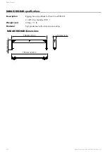
Page 131: ...e for vertical deployment of Kara IIi and SB18 IIi 2 Ø19 mm shackles WLL 3 25 t Weight net 21 kg 46 lb Material high grade steel with anti corrosion coating KARAIIi BUMP dimensions 700 mm 27 6 in 707 mm 27 8 in 80 mm 3 1 in Kara IIi owner s manual EN version 2 0 131 ...

Page 132: ...r and pullback for Kara IIi and SB18 IIi 2 Ø12 mm shackles WLL 1 t Weight net 4 8 kg 11 lb Material high grade steel with anti corrosion coating KARAIIi RIGBAR dimensions 738 mm 29 in 210 mm 8 3 in 50 mm 2 in 758 mm 29 8 in 132 Kara IIi owner s manual EN version 2 0 ...

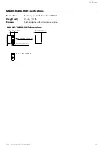
Page 133: ...rackets for Kara IIi and SB18 IIi Weight net 0 5 kg 1 1 lb Material high grade steel with anti corrosion coating KARAIIi FIXBRACKET dimensions Ø 11 5 mm 0 45 in Ø 6 9 mm 0 27 in 35 mm 1 4 in 60 mm 2 4 in 75 mm 3 in 6 9 mm 0 27 in Kara IIi owner s manual EN version 2 0 133 ...

Page 134: ...ht net 0 6 kg 1 3 lb Material high grade steel with anti corrosion coating KARAIIi TILTBRACKET dimensions Ø 11 5 mm 0 45 in Ø 6 9 mm 0 27 in 35 mm 1 4 in 60 mm 2 4 in 75 mm 3 in 6 9 mm 0 27 in 60 mm 2 4 in Ø 6 9 mm 0 27 in 187 mm 7 4 in Ø 11 5 mm 0 45 in 56 mm 2 2 in 134 Kara IIi owner s manual EN version 2 0 ...

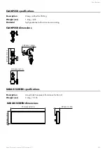
Page 135: ...teel with anti corrosion coating CLAMP250 dimensions 167 mm 6 6 in 103 mm 4 1 in 227 mm 8 9 in KARAIIi SCREEN speci cations Description Acoustically transparent front screen for Kara IIi Weight net 2 4 kg 5 3 lb KARAIIi SCREEN dimensions 253 mm 10 in 714 mm 28 1 in 97 mm 3 8 in Kara IIi owner s manual EN version 2 0 135 ...

Page 136: ...Ii SCREEN speci cations Description Acoustically transparent front screen for SB18 IIi Weight net 2 7 kg 6 lb SB18IIi SCREEN dimensions 714 mm 28 1 in 539 mm 21 2 in 97 mm 3 8 in 136 Kara IIi owner s manual EN version 2 0 ...

Page 137: ...tation In standard orientation the inter element angle can be set between 5 and 15 in 2 5 steps FRONT A A 0 A 2 5 A 5 A 7 5 A 10 A 12 5 A 15 B1 B2 B 2 5 B 5 AB1 AB2 0 KARAIIi TILT holes used in standard position inter element angle Linking points 0 2 5 5 7 5 10 12 5 15 0 with reduced space between enclosures 2 5 5 front A B1 B1 On SB18 IIi rear A angle set B2 B2 front AB1 AB1 AB1 On Kara IIi rear ...

Page 138: ...n 2 5 steps FRONT A A 10 A 12 5 A 15 A 17 5 A 20 A 22 5 A 25 B1 B2 B 7 5 B 5 AB1 AB2 10 KARAIIi TILT holes used in reversed position inter element angle Linking points 5 7 5 10 12 5 15 17 5 20 22 5 25 front B2 A angle set On SB18 IIi rear B1 A front B angle set or AB2 10 AB1 On Kara IIi rear AB1 AB1 138 Kara IIi owner s manual EN version 2 0 ...

Page 139: ...ovides the recommended maximum length for loudspeaker cables depending on the cable gauge and on the impedance load connected to the ampli er recommended maximum length cable gauge 8 Ω load 4 Ω load 2 7 Ω load mm 2 SWG AWG m ft m ft m ft 2 5 15 13 30 100 15 50 10 33 4 13 11 50 160 25 80 17 53 6 11 9 74 240 37 120 25 80 Use the more detailed L Acoustics calculation tool to evaluate cable length and...

Page 140: ... in 1039 mm 40 90 in 3 mm 0 11 in 3 m m 0 1 1 in 329 2 mm 12 95 in 143 4 mm 5 63 in 339 2 mm 13 35 in 201 8 mm 7 91 in 4 x M6 inserts per side 4 x M6 inserts per side 660 9 mm 25 98 in 492 mm 19 37 in Kara IIi SB18 IIi Weight without rigging plates Kara IIi 21 kg 46 lb SB18 IIi 48 kg 106 lb 140 Kara IIi owner s manual EN version 2 0 ...

Page 141: ... of the array Recommended screws for a 3 mm thickness metal sheet M6x18 Adapt the length of the screws according to the thickness of the sheet Prevent bolts from loosening threadlocker spring washer Threaded inserts Maximum loads Maximum tensile load 1160 N Maximum shear load 4250 N Recommended torque 5 N m Kara IIi owner s manual EN version 2 0 141 ...

Page 142: ...L Acoustics 13 rue Levacher Cintrat 91460 Marcoussis France 33 1 69 63 69 63 info l acoustics com www l acoustics com ...

Reviews: