K1_RM_EN_2-0
w w w . l - a c o u s t i c s . c o m
47
47
47
47
2.
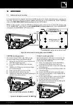
Check the inter-enclosure connections in ARRAY#1 (repeat for each side):
a.
For both front connecting points, verify that the front arm is open and locked to 2 KARA by 2 R-BLP inserted
in
yellow link holes
.
b.
For both rear connecting points, verify that the angle arm cursor is aligned with the
0°
angle value and locked
to 2 KARA by 2 R-BLP, the upper one inserted into a
yellow link hole
and the bottom one inserted into angle
hole
0°/2°/4°
.
Figure 44: Inter-enclosure connection check for ARRAY#1
3.
On KARA#1, take the 4 arms out as follows (repeat for each side):
a.
Remove the front top R-BLP from storage position, rotate the front arm up, slide it down, and secure by re-
inserting the R-BLP into the
yellow link hole
.
b.
Remove the rear top R-BLP, slide the angle arm so as to align the cursor with angle value
7.5°
or
10°
, and
secure by re-inserting the R-BLP into angle hole
1°/3°/5°/7.5°/10°
.
Figure 45: Setting the KARA#1 arms
a.
L
b.
L
b.
ARRAY#1
KARA#1
KARA#2
KARA#3
a.
Link
0°
Summary of Contents for K1
Page 2: ...w w w l a c o u s t i c s c o m ...
Page 68: ...w w w l a c o u s t i c s c o m ...
Page 69: ...w w w l a c o u s t i c s c o m ...
Page 70: ...w w w l a c o u s t i c s c o m ...


