28 | kvm-tec
kvm-tec | 29
2. INSTALLATION eXTeNDeR
2. INSTALLATION eXTeNDeR
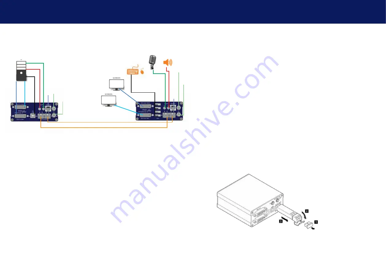
2.7 QUICk InsTallaTIon maXfleX dUal fIbeR
local / CPU – remote / CON
1.
Connect the CON / Remote and the CPU / Local Unit to the included 12V 1A
power supply.
2.
Now connect the USB cable to a USB port on your PC and connect the other
end of the USB cable to the CPU / Local Unit. Connect keyboard and mouse to
the CON / Remote Unit.
3.
Connect the CPU / Local and the CON / Remote Unit with a network cable.
4.
Now connect the DVI cable to the DVI socket of the PC and the other end to
the DVI socket of the CPU / Local Unit (PC-in).
5.
Now connect the DVI cable to the DVI socket of the PC and the other end to
the DVI socket of the CPU / Local Unit (PC-in 2). Then connect the monitor with
the DVI cable to the CON / Remote Unit.
6.
Connect PC audio/out with the audio cable to local audio/in. Connect audio/
out via the audio cable
7. Almost done! Connect the audio cable local audio/out to the PC audio/in and
remote audio/out with audio cable to the microphone
8. Using a switch: Connect all endpoints to the switch. Ensure that all connec
-
tions have a bandwith of 1Gbit/sec. For video sharing the network has to
support IGMP snooping.
Power plug 12V 1A
Power plug
12V 1A
USB to PC
DVI in 1 from PC
DVI to Monitor 1
USB from
Keyboard and mouse
OM3-Fiber cable up to 500m/1640ft
OM3-Fiber cable up to 500m/1640ft main link
Audio from PC
Audio to PC
Audio to speaker
Audio from microphone
RS232 plug
RS232 plug
DVI in 2 from PC
DVI to Monitor 2
Power plug 12V 1A
(redundant)
Power plug
12V 1A (redundant)
2.8 sTaRT UP
To start up the system without switch:
1. Make sure that the two monitors and the computer are switched on.
2. If you are using a Network Switch, connect the power supply to an earthed wall socket.
3. Connect both extender
power supplies
(C) to an earthed wall socket. Both extenders will
start an initialisation process. The red status LED blinks a few seconds. After a few seconds
the status LED lights green. The monitor will displays your computer’s desktop or any open
applications.
2.9 RePlaCInG The sfP modUle
The MA1-F is delivered with a multimode SFP module.
To replace an sfP module with a different sfP module:
1. Remove the black dust protector from the SFP module.
2. Pull the metal latch of the SFP module forwards until it is at a right angle.
3. Replace the SFP module with the other module. Put the metal latch back in position. Only
use SFP modules from kvm-tec, or recommended by kvm-tec.


