24 | kvm-tec
kvm-tec | 25
2. INSTALLATION eXTeNDeR
2. INSTALLATION eXTeNDeR
2.3 InsTallInG The eXTendeR
WaRnInG!
Read and understand all safety information before installing the product.
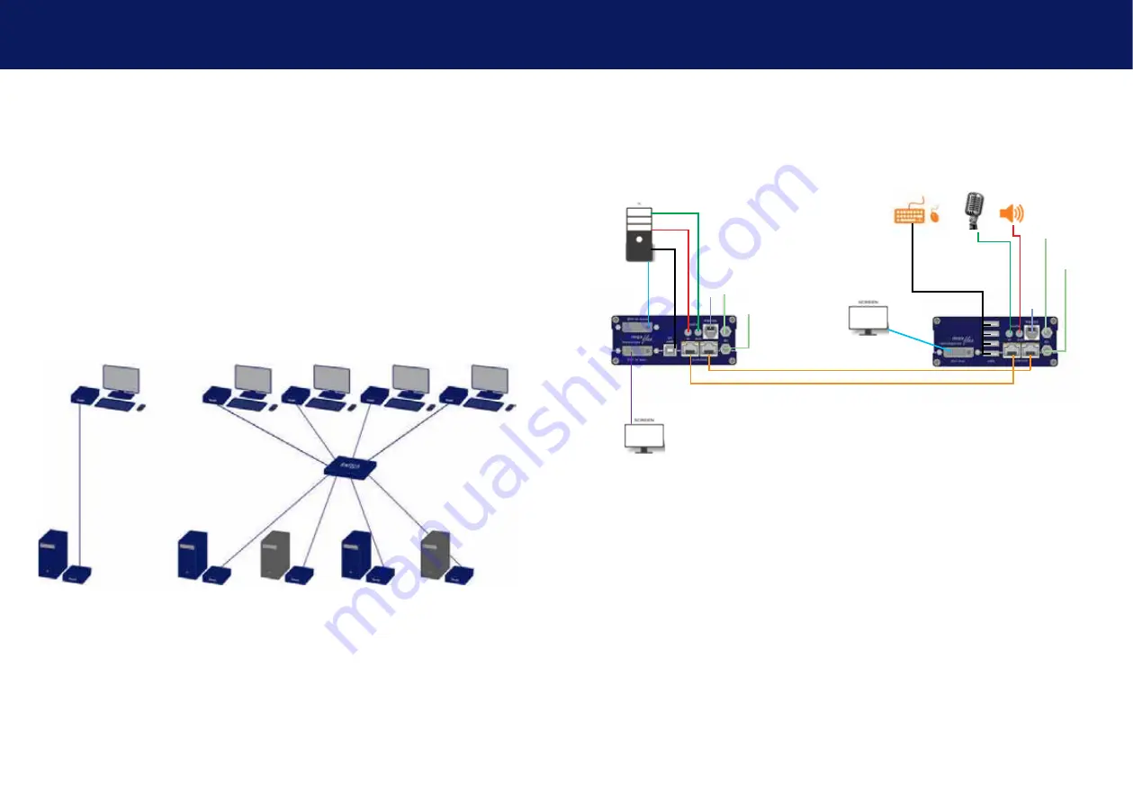
The units can be set up to access one host computer, or to access numerous host computers.
In the case of the latter, an additional Network Switch must be installed. With a Network Switch,
each user can gain quick access to any of the required computers.
point to point connection & matrix switching system
2.4 QUICk InsTallaTIon maXfleX sInGle
local / CPU – remote / CON
Power plug 12V 1A
Power plug
12V 1A
USB to PC
DVI in from PC
DVI to Monitor
USB from Keyboard and mouse
Network cable CAT5e/6/7/ up to 150m/492ft (redundant)
D
VI out
to Monitor
Network cable CAT5e6/7/ up to 150m/492ft main link
Audio from PC
Audio to PC
Audio to speaker
Audio from microphone
RS232 plug
RS232 plug
Power plug 12V 1A
(redundant)
Power plug
12V 1A (redundant)
1.
Connect the CON / Remote and the CPU / Local Unit to the included 12V 1A
power supply.
2.
Now connect the USB cable to a USB port on your PC and connect the other
end of the USB cable to the CPU / Local Unit. Connect keyboard and mouse to
the CON / Remote Unit.
3.
Connect the CPU / Local and the CON / Remote Unit with a network cable.
4.
Now connect the DVI cable to the DVI socket of the PC and the other end to
the DVI socket of the CPU / Local Unit (PC-in).
5.
Almost done! Connect the audio cable local audio/out to the PC audio/in and
remote audio/out with audio cable to the microphone
6.
Using a switch: Connect all endpoints to the switch. Ensure that all connec
-
tions have a bandwith of 1Gbit/sec. For video sharing the network has to
support IGMP snooping.


