


11
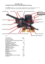
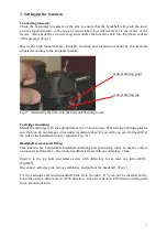
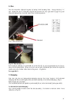
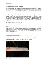
8. Bias
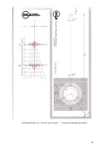
The bias should be adjusted roughly according to the tracking force. Using Allen key 1.5
mm, unlock the screw on the bias weight and position it to the equivalent of gap X to your
chosen tracking force. Lock the screw back, when in position.
Fig. 9 Bias adjustment
Fig. 9a Bias distance “X”
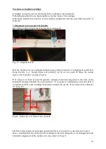
For maximum tracking, it is advisable to set the bias by use of an appropriate test record, ie.
those with tracking bands. Please do not use test records with blank space where the tip of the
needle sits on the surface rather than in the groove. (Fig.9&9a)
See appendix 3.
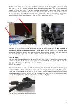
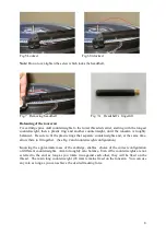
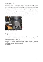
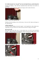
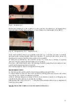
9. Damping
This tone arm has two independent damping systems. The lower trough is for horizontal
damping and the second trough on the arm tube assembly is for vertical damping. (Fig.1)
Both troughs are removable.
The horizontal holder with paddle is permanently fixed on the horizontal bearing assembly.
Vertical& horizontal damping:
The vertical paddle is inserted after the tube assembly. Fix holder in the hole with 1.5 mm
Allen key. (Fig 10)
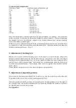
X
P
mm gr
0
1.00
4
1.50
8
2.00
10
2.25
12
2.50
x
Cue device lock
bias lock
X


