ELK-319WS Wireless Window and Shock Sensor
Description
The ELK-319WS is a Supervised, Wireless Window Sensor designed
to detect the opening of a window or vibrations made by an intruder
attempting to break the window. A built-in reed switch monitors
windoe movement and a piezo shock sensor monitors vibrations.
The sensitivity and range of the piezo shock is adjustable.
When the sensor activates it transmits a signal to the control
panel. Additional transmitted signals include: restoral, supervisory,
tamper and low battery (as needed). Sensor is powered by two (2)
replaceable 3-V lithium coin-cell batteries. It is compatible with Elk’s
319MHz Receivers/Panels as well as many other panels that operate
on the 319.5MHz Frequency and adhere to the ITI/Interlogix protocol.
Specifications
RF frequency: 319.5 MHz
Compatibility: ELK-319 Panel/Receivers & others that operate on
Freq. 319.5MHz and use the ITI/Interlogix protocol
Battery type: Two (2) 3V lithium coin-cell
(Panasonic or Varta Model CR2032)
OperatingTemp Range: 32 to 120°F (0 to 49°C)
Storage Temp Range: -30 to 140°F (-34 to 60°C)
Relative Humidity:
95% non-condensing
Dimensions
2.25” L x .1.0 x 0.50” in. (L x W x D)
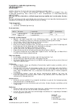
Programming (Enrollment)
The following is a general guideline for programming (enrolling) this
sensor into the receiver or panel. For more detailed steps please
refer to the receiver or panel instructions.
NOTE: THIS SENSOR ENROLLS DIFFERENTLY FROM OTHERS
The reed and piezo shock are two (2) different sensors and require
their own TXID identifier and zone in the alarm panel.
The TXID printed on the sensor label is for the piezo shock sensor.
The TXID for the reed sensor will be the shock TXID plus 1.
Example: If shock TXID is 0A62CC7 the reed TXID will be A062CC8
1. Power up the sensor by pulling and removing both battery isolator
tabs. DO NOT REMOVE the sensor cover. It will be done in 4.
2. Place the panel into the Program mode and proceed to the
WIRELESS SETUP menu.
3. Select the appropriate zone/sensor location number for the piezo
shock sensor.
4. Start the panel sensor Enroll process. When the panel prompts
to trip the sensor for learning do the following:
- Remove sensor cover to activate the tamper. The panel should
acknowledge the shock has been learned by keypad display and/
or audio alert (depending on panel). If enrollment fails try putting
the cover back on and repeating steps 3 and 4.
5. Advance to next zone/sensor location to enroll the reed switch.
6. Remove both batteries from the sensor.
7. Start the panel Enroll process. When the panel prompts to trip
the sensor for learning do the following:
- Hold the tamper plunger down with one finger while inserting one
of the batteries. The panel should acknowledge the magnetic
reed switch has been learned by keypad display and/or audio
alert (depending on panel). If enrollment does not succeed
remove both batteries and repeating steps 5 thru 7.
NOTE:
Loop assignment must be set for “ 2 “ on both sensor zones.
8. Proceed to the zone programming and assign the zone definition
for each enrolled sensor.
9. Exit programming mode when finished.
TM
Interlogix is a registered trademark belonging to United Technologies.
Installation Guidelines
• Sensor should be mounted window frame and magnet on the
moveable part of the window. Sensor is recommend for wood
or vinyl windows only.
• Attaching sensor to a metal surface can negatively affect the
transmit range and magnet gap performance. Some metallic
surfaces may be acceptable if range and gap testing are good.
• Always attach the sensor temporarily at the desired location and
successfully range test with the panel/receiver prior to drilling any
holes or mounting permanently.
• Install the sensor within 100 ft. of the receiver or panel.
• Align magnet directly opposite the top LEFT edge of the sensor
with a gap of 5/16” (8 mm) or less for wood surfaces and 1/4” (6
mm) or less for non-wood surfaces.
Note:
Gap between sensor and magnet must never exceed 3/8”.
• After mounting is completed, retest the sensor using the test
procedures which follow.
Mounting the Sensor
Sensor may be mounted using screws or double sided foam tape.
Screws
Separate the sensor and magnet from their mounting bases and
place the bases in the desired location. Secure using the supplied
screws. Re-attach the sensor and magnet onto their bases making
sure the alignment marks on the sensor and magnet are facing
one another.
Double-Sided Tape
It is not necessary to separate the sensor and magnet from their
bases when using double sided tape. Make certain the window
mounting surfaces & surfaces of the sensor and magnet are clean,
smooth and dry.