14
Inbetriebnahme
Commissioning
4.4 Entlötkolben X-Tool
• Prüfen Sie, ob der Lotsammelfilter (Abb. 2/
Pos.4) sowie der Partikelfilter (Abb. 2/Pos. 2)
im Restlotbehälter (Abb. 2/Pos. 3) eingebaut
sind.
• Stellen Sie sicher, daß der Restlotbehälter
(Abb. 2/Pos. 3) in den Entlötkolben einge-
setzt ist.
• Prüfen Sie, ob die von Ihnen gewünschte
Entlötspitze (Abb. 4/Pos. 5) in den Wärme-
speicher (Abb. 4/Pos. 4) eingesetzt ist.
• Um Leckagen zu vermeiden, achten Sie
bitte darauf, daß alle Komponenten wie
Entlötspitze, Lotsammelbehälter, Dichtungen,
Vakuumschlauch und Filter fest und luftdicht
miteinander verbunden sind.
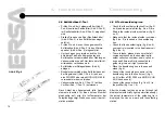
• Entlötkolben im Ablageständer (Abb.6)
ablegen.
• Rundsteckerverbinder des Entlötkolbens mit
der Regeleinheit (Abb. 1/Pos. 4) (es kann
eine DIG 2000 oder eine MICRO-CON 60 iA
verwendet werden) verbinden.
• Vakuumschlauch (Abb. 1/Pos. 12) auf den
Vorfilter (Abb. 1/Pos. 13) aufstecken.
Nach Ablauf des Anzeigetests (alle Anzeige-
elemente leuchten für einen kurzen Moment
gleichzeitig auf) wird die Ist-Temperatur der
Lötspitze angezeigt. Sie können nun mit der Löt-
station arbeiten.
4.4 X-Tool desoldering iron
• Check that the solder collection filter (fig. 2/
no. 4)and the particle filter (fig. 2/no. 2) are
fitted in the residual solder container (fig. 2/
no. 3).
• Make sure that the residual solder container
(fig. 2/no. 3) is inserted in the desoldering
iron.
• Check that the desoldering tip (fig. 4/no. 5)
you require is inserted in the heat reservoir
(fig. 4/no. 4).
• To avoid leaks, please make sure that all
components such as the desoldering tip,
solder collection container, seals, vacuum
hose and filters are firmly connected to-
gether to give an air-tight connection.
• Place the desoldering iron in the support
stand (fig. 6).
• Connect the round plug connector of the
desoldering iron to the control unit (fig. 1/
no. 4) (either a DIG 2000 or a MICRO-CON
60 iA can be used).
• Connect the vacuum hose (fig. 1/no.12) to
the prefilter (fig. 1/no. 13).
After the display test has been run through (all
display elements briefly light up simultaneously),
the actual temperature of the soldering tip is
displayed. You can now work with the soldering
station.
4.
Abb. 6/Fig. 6


