6. Fehlerdiagnose
und -behebung
Error Diagnosis
and Remedy
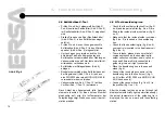
• Öffnen Sie das Gehäuse (2 Schrauben auf Front-
seite, 2 Schrauben im Gehäuseoberteil (Abb.4/
Pos. 2) mit einem Torxschlüssel, Schlüsselweite 6.
• Nehmen Sie die Griffhälfte (Abb. 4/Pos. 3),
in der der Arretierknopf (Abb. 4/Pos. 1) sitzt, ab.
• Messen Sie die Heizelemente (Abb. 4/Pos. 6)
nochmals, um eventuell zu ermitteln, welches
Heizelement defekt ist.
• Ziehen Sie die Flachsteckverbindungen (Abb.4/
Pos. 3) am defekten Heizeinsatz ab. Beachten
Sie, daß beim Wechsel des Heizeinsatzes
mit angebautem Thermoelement dieses erst
am Wärmespeicher aus der Nut (Abb. 4/Pos 7)
aufgebogen werden muß.
• Heben Sie den Heizeinsatz am Leiterplättchen
(Abb. 4/Pos. 5) leicht an und ziehen Sie
das Ganze nach hinten heraus.
• Setzen Sie den neuen Heizeinsatz in umge-
kehrter Reihenfolge wieder ein und achten Sie
auf den richtigen Anschluß der elektrischen
Verbindungen (Abb.3).
• Nach Wechsel des Thermoelements muß
dieses am Wärmespeicher wieder in die vorge-
sehene Vertiefung (Abb. 4/Pos. 7) eingedrückt
werden. Verwenden Sie dazu einen Schrauben-
dreher oder ähnliches.
Achtung:
Das Thermoelement darf nicht ge-
quetscht oder scharfkantig abgebogen werden.
Sollten Sie ein Problem nicht lösen können, so
schicken Sie das Gerät bitte frei, komplett und
in der Originalverpackung an ihren zuständigen
Händler oder den Hersteller.
• Use a size 6 Torx driver to open the housing
(2 screws on the front panel, 2 screws on the top
part of the housing (fig. 4/no. 2).
• Remove the handle halves (fig. 4/no. 3) in which
the locking knob (fig. 4/no. 1) is mounted.
• Measure the heating elements (fig. 4/
no. 6) again since this may indicate which
heating element is defective.
• Disconnect the tab connectors (fig. 4/no. 3) from
the defective heating insert. Please note
that if you change the heating insert with
the thermocouple fitted, you will have to
bend the thermocouple to get it out of the slot
(fig. 4/Pos 7).
• Slightly lift the heating insert by the chip
(fig. 4/no. 5) and pull out the complete
subassembly.
• Insert the new heating insert in reverse
order. Make sure that you reconnect the
electrical connections correctly (fig. 3).
• After changing the thermocouple, you have
to press it back into the indentation (fig. 4/
no. 7) on the heat reservoir. Use a screwdriver
or a similar tool to do this.
Important:
Do not crush the thermocouple or
bend it at an acute angle.
If you encounter a problem which you cannot
solve, please send the unit back to your dealer
or the manufacturer with the required postage.
The unit should be complete and in its original
packaging.
22


