6. Fehlerdiagnose
und -behebung
Error Diagnosis
and Remedy
6.4.2 Prüfung des
Thermoelementfühlers
Wird bei heißer Entlötspitze in der Istwertanzei-
ge der Regelungseinheit nur eine niedrige, z.B.
Raumtemperatur, angezeigt, deutet dies auf ein
defektes Thermoelement hin.
Eine hohe Sollwertanzeige bei nichtbeheizter
Entlötspitze ist Hinweis auf einen Thermo-
elementbruch.
In beiden Fällen muß der Thermoelementfühler
gewechselt werden.
Da Thermoelementfühler und Heizkörper
zusammenmontiert geliefert werden, muß der
komplette Bausatz gewechselt werden. Führen
Sie den Wechsel selbst durch, dann gehen Sie
wie in Kap. 6.4.3 beschrieben vor.
6.4.3 Wechseln von Heizelement und
Thermoelementfühler
• Schalten Sie die Geräte am Netzschalter aus
(Abb.1/Pos.11) und ziehen Sie den 8-poligen
Rundstecker des Entlötkolbens (Abb.1/Pos.2)
ab.
Achtung:
Lassen Sie das Gerät einige Minu-
ten abkühlen.
• Ziehen Sie die Entlötspitze mit Hilfe des
Spitzenhalteblechs heraus.
• Entnehmen Sie den Restlotbehälter (Abb.1/
Pos. 8) siehe auch Kap. 7.1.1.
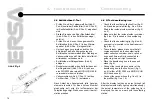
• Entspannen Sie das Ventil, indem Sie den
Arretierknopf (Abb. 4/Pos.1) drücken.
6.4.2 Testing the
thermocouple sensor
An indication of a defect in the thermocouple
is that only a low temperature, e.g. room tem-
perature, is shown on the actual value display of
the control unit when the desoldering tip is hot.
An indication of a breakage in the thermocouple
is that a high nominal value is displayed although
the desoldering tip is not being heated.
The thermocouple sensor must be replaced in
either case.
The thermocouple sensor and heating element
are supplied as one subassembly, so it is
necessary to replace them as a complete set.
Proceed as described in chap. 6.4.3 if you are
going to change them yourself.
6.4.3 Changing the heating element
and thermocouple sensor
• Switch off the unit at the power switch (fig. 1/
no. 11) and disconnect the 8-pin round
connector for the desoldering iron (fig. 1/no. 2).
Important:
Leave the unit for a few minutes
to cool down.
• Pull out the desoldering tip using the tip holder
plate.
• Remove the residual solder container
(fig. 1/no. 8), see also chap. 7.1.1.
• Release the valve by pressing the locking knob
(fig. 4/no. 1).
21


