3 - 25
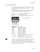
3.7.4. Analog inputs, 0...10 V, 10 bit, single-ended
In its basic configuration, the KUAX 680C is equipped with
four analog inputs. Further analog inputs can be added as plug-
in modules.
Signal line connection
Signal line connection
Signal line connection
Signal line connection
Signal line connection
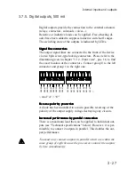
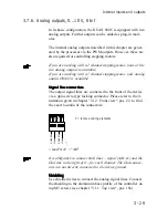
The input signal lines are connected to the front of the device
via an 8pin screw-type locking connector. Please refer to the il-
lustration given in chapter "3.1.2. Front view", pos. 23, to find
the exact location of the connectors.
A
E
00.
00
Gn
d
A
E
00.
01
Gn
d
A
E
00.
02
Gn
d
A
E
00.
03
Gn
d
K
K
C = remove coding element
*)
read "AE" = "AI"
It is obligatory to connect both lines – signal (AIxx.xx) and the
Gnd line to the right of it – for each channel. The Gnd connec-
tors are not directly connected to the device ground.
Shielding
Shielding
Shielding
Shielding
Shielding
Use shielded wires to connect the analog signal lines. Connect
the shielding to the aluminium base profile of the controller us-
ing M3 screws (see chapter "3.1.1. Top view", pos. 10a).
Internal inputs and outputs
*)
C
C
Summary of Contents for KUAX 680C
Page 10: ...Contents 8 Table of contents...
Page 12: ...1 2 Introduction...
Page 90: ...4 36 Description of the commands...
Page 99: ...4 45 Software 4 7 10 Module hierarchy example for different module calls...
Page 102: ...5 2 Networking...
Page 132: ...6 30 Examples...
Page 160: ...A 4 Appendix...
Page 164: ...C 2 Appendix...
Page 180: ...Index 6 Index...


