Contents - 2
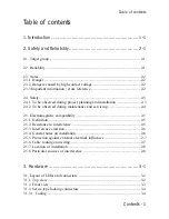
Table of contents
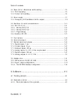
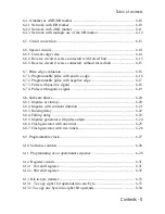
3.2. Basic device: dimensions and mounting ....................................................... 3-5
3.2.1. Wall mounting ............................................................................................ 3-5
3.2.2. Carrier rail mounting .................................................................................. 3-6
3.3. Power supply .................................................................................................. 3-7
3.3.1. Emergency Off installation for the outputs ................................................ 3-8
3.4. Interfaces for serial communication ........................................................... 3-11
3.4.1. RS 232 (V.24) .......................................................................................... 3-11
3.4.1.1. Interface RS 232/1 ................................................................................ 3-12
3.4.1.2. Interface RS 232/2 ................................................................................ 3-12
3.4.1.3. Programming ........................................................................................ 3-12
3.4.2. Interface RS 485 ...................................................................................... 3-13
3.5. User memory ............................................................................................... 3-14
3.6. System messages ......................................................................................... 3-15
3.7. Internal inputs and outputs ......................................................................... 3-16
3.7.1. Digital inputs, 5 ms .................................................................................. 3-17
3.7.2. Counter inputs, 10 µs ............................................................................... 3-19
3.7.3. Interrupt inputs, 300 µs ............................................................................ 3-22
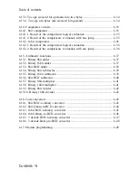
3.7.4. Analog inputs, 0...10 V, 10 bit, single-ended ......................................... 3-25
3.7.5. Digital outputs, 500 mA .......................................................................... 3-27
3.7.6. Analog outputs, 0...10 V, 8 bit ................................................................... 3-2
3.8. Module slots ................................................................................................ 3-31
3.8.1. Differences to the KUAX 680I ................................................................ 3-32
3.8.2. Input / output configuration ..................................................................... 3-33
3.8.2.1. The KUBES Module Configurator ....................................................... 3-34
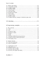
4. Software .................................................................... 4-1
4.1. Working principle .......................................................................................... 4-1
4.2. Operands overview ........................................................................................ 4-2
4.2.1.1. Short description of the operands ............................................................ 4-3
Summary of Contents for KUAX 680C
Page 10: ...Contents 8 Table of contents...
Page 12: ...1 2 Introduction...
Page 90: ...4 36 Description of the commands...
Page 99: ...4 45 Software 4 7 10 Module hierarchy example for different module calls...
Page 102: ...5 2 Networking...
Page 132: ...6 30 Examples...
Page 160: ...A 4 Appendix...
Page 164: ...C 2 Appendix...
Page 180: ...Index 6 Index...


