


2-M2
ST
α
-30 · ST
α
-35, WSM
CLUTCH
2. OPERATION
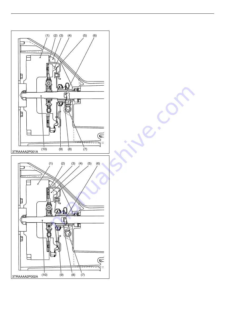
■
Clutch “Engaged”
When the clutch pedal is not depressed, the clutch
release bearing (9) and the fingers of diaphragm spring
(5) are not connected to each other.
Accordingly, the pressure plate (4) is tightly pressed
against the flywheel (1) by the diaphragm spring (5). As
a result, rotation of the flywheel (1) is transmitted to the
transmission through the clutch shaft (10) due to the
frictional force among the flywheel (1), clutch disc (2) and
pressure plate (4).
W1012698
■
Clutch “Disengaged”
When the clutch pedal is depressed, the clutch pedal
rod is pulled to move the clutch rod (7). Then, the
release fork (6) pushes the release hub (8) and release
bearing (9) toward the flywheel. Simultaneously, the
release bearing (9) pushes the diaphragm spring (5).
As the pressure plate (4) is pulled by the diaphragm
spring (5), the frictional force among the flywheel (1),
clutch disc (2) and pressure plate (4) disappears.
Therefore, rotation of the flywheel (1) is not
transmitted to the clutch disc (2), and then the rotation of
the clutch shaft (10) stops.
W1012945
(1) Flywheel
(2) Clutch Disc
(3) Clutch Cover
(4) Pressure Plate
(5) Diaphragm Spring
(6) Release Fork
(7) Clutch Rod
(8) Release hub
(9) Release Bearing
(10) Clutch Shaft
(1) Flywheel
(2) Clutch Disc
(3) Clutch Cover
(4) Pressure Plate
(5) Diaphragm Spring
(6) Release Fork
(7) Clutch Rod
(8) Release hub
(9) Release Bearing
(10) Clutch Shaft
KiSC issued 11, 2006 A
Summary of Contents for WSM STa-30
Page 1: ...ST 30 ST 35 WORKSHOP MANUAL TRACTOR KiSC issued 11 2006 A...
Page 7: ...5 ST 30 ST 35 WSM SAFETY INSTRUCTIONS KiSC issued 11 2006 A...
Page 8: ...6 ST 30 ST 35 WSM SAFETY INSTRUCTIONS KiSC issued 11 2006 A...
Page 12: ...10 ST 30 ST 35 WSM DIMENSIONS DIMENSIONS KiSC issued 11 2006 A...
Page 13: ...G GENERAL KiSC issued 11 2006 A...
Page 58: ...1 ENGINE KiSC issued 11 2006 A...
Page 117: ...2 CLUTCH KiSC issued 11 2006 A...
Page 118: ...CONTENTS MECHANISM 1 FEATURES 2 M1 2 OPERATION 2 M2 KiSC issued 11 2006 A...
Page 136: ...3 TRANSMISSION KiSC issued 11 2006 A...
Page 158: ...3 S1 ST 30 ST 35 WSM TRANSMISSION 1 TROUBLESHOOTING KiSC issued 11 2006 A...
Page 159: ...3 S2 ST 30 ST 35 WSM TRANSMISSION KiSC issued 11 2006 A...
Page 192: ...4 REAR AXLE KiSC issued 11 2006 A...
Page 193: ...CONTENTS MECHANISM 1 STRUCTURE 4 M1 2 OPERATION 4 M2 KiSC issued 11 2006 A...
Page 201: ...5 BRAKES KiSC issued 11 2006 A...
Page 202: ...CONTENTS MECHANISM 1 FEATURES 5 M1 2 OPERATION 5 M2 KiSC issued 11 2006 A...
Page 211: ...6 FRONT AXLE KiSC issued 11 2006 A...
Page 212: ...CONTENTS MECHANISM 1 STRUCTURE 6 M1 2 FRONT WHEEL ALIGNMENT 6 M2 KiSC issued 11 2006 A...
Page 231: ...7 BI SPEED TURN KiSC issued 11 2006 A...
Page 255: ...8 STEERING KiSC issued 11 2006 A...
Page 277: ...9 HYDRAULIC SYSTEM KiSC issued 11 2006 A...
Page 313: ...10 ELECTRICAL SYSTEM KiSC issued 11 2006 A...
Page 316: ...10 M2 ST 30 ST 35 WSM ELECTRICAL SYSTEM KiSC issued 11 2006 A...
Page 317: ...10 M3 ST 30 ST 35 WSM ELECTRICAL SYSTEM KiSC issued 11 2006 A...


