19 / 34
Danger!
Work in containers involves the danger of intoxication and suffocation. No work
is allowed to be carried out unless by taking suitable personal protective
measures (e.g. respiratory protection apparatus, protective outfit etc.).
Warning
– Danger of Explosion!
Inside the container, there is danger of an explosive atmosphere. Corresponding
measures for preventing sparking should be taken. No work is allowed in this area unless
by technically skilled staff in accordance with applicable safety regulations.
Employment and Field of Application
The FFG-T...EX system is available for employment in varying container heights of between 200 and
6000 mm.
Flange-type or screw-type designs are available allowing a stepless positioning of the FFG-
T...EX within the container, depending on the design thereof.
Probe tube and float can be installed down
to the screw element or flange in areas exposed to danger of explosion, in which electric units of the
category 1 / 2 (zone 0) are required. In respect of the bypass type, the complete system is allowed to be
installed in areas exposed to danger of explosion that require electric unit of category 2 (zone 1). The
sensor head of the level sensor can be operated at ambient temperatures of between
–40 °C to + 85
°C, while the sensor tube is operable within a temperature range of between
–25 °C to + 150 °C. The
permitted process temperatures in case of employment in zones subject to danger of explosion that
require operating units of categories 1 / 2 or 2, are set out in the Tables.
The technical specifications set out in these operating instructions should be observed.
Design and Description of Functions
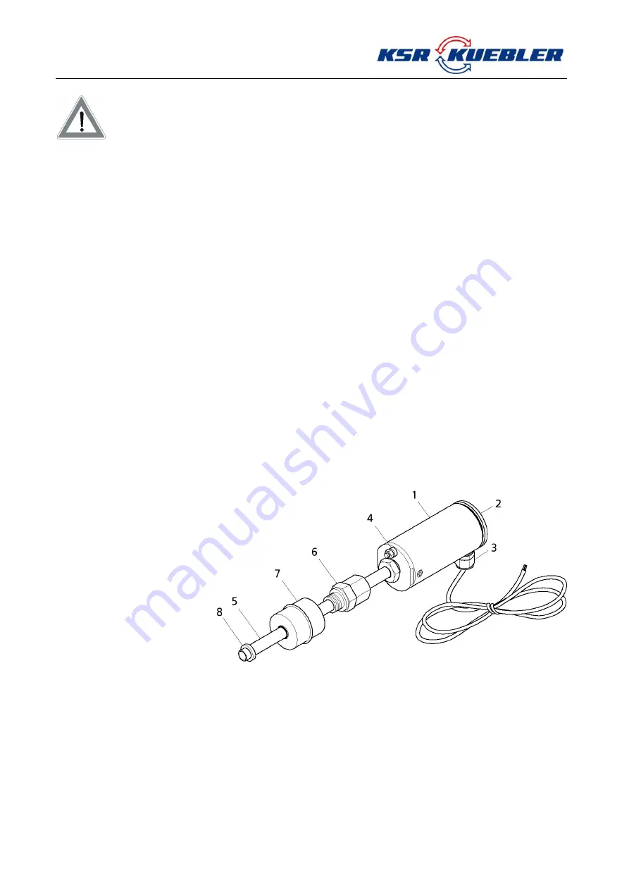
The design of the FFG-T...EX system is shown in figure 1 in the form of embodiment furnished with a
screwed-in element. Provided in the probe head (1) of the FFG-T..:EX system is the area of connection
and adjustment protected by lid (2). The electrical connection is via an M16x1.5 cable gland (3) at the top
of the probe head while the earth connection (4) is at the bottom of the probe head. Seated on the probe
tube (5) for vertically adjustable assembling purposes, within the container, is a compression fitting (6)
(G1/2, W27) or a flange (not
shown). The float (7) serves
for continuously gauging the
product level or separating
layer, and is held on the
probe tube by a guiding or
locking ring (8) etc.
The level sensor shown in
figure 2 serves for the
continuous measurement of
fluids. To transmit the liquid
level value to the sensor, a
float is sliding on the sensor
tube. The operating principle of the sensor is based on the magnetostriction effect. The float
contains a magnet while a wire made of magnetostrictive material is installed under tension inside
the sensor tube. The magnetic field of the float is twisting the cable. A second, temporary
magnetic field is generated along the cable by a current pulse within the cable. The superposition
of the two magnetic fields will release a mechanical wave on the wire. At the end of the wire within
the sensor head, the mechanical wave is converted by a piezo-ceramic transducer into an
electrical signal. The starting point of the mechanical wave and, hence, the float position is then
determined by measuring the transit time. The results of such measurements are feasibility-tested
by a microcontroller located in the sensor head and are then converted into a current value by a
DA-transformer. The sensor is provided with a 2-wire connection so that the current consumption
indicates the position of the float at the same time. The current values are restricted to a range of
between 3.5 ...23mA.
fig. 1: Level Sensor FFG-T...EX


