background image

23

SMARTRONIC MA

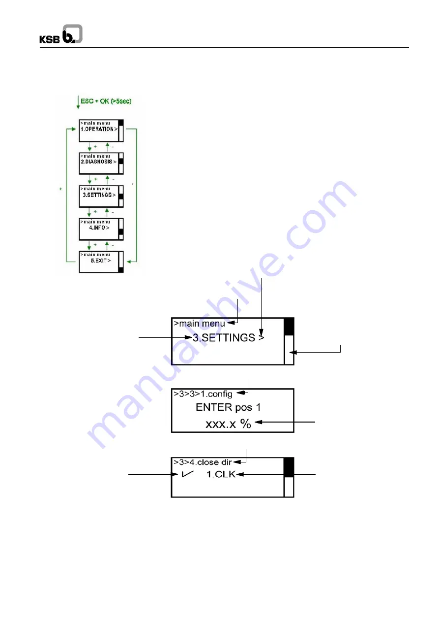
VI -  3 Submenu screen

To access  the submenus:
-   Press  buttons  <OK>  and <ESC>  simultaneously for 5 seconds.
-   Navigate  with the <+> and <-> buttons.
-   Validate  with <OK>.
-   Cancel  with <ESC>.

Indicates  the presence 
of a submenu

Path

Submenu  title

Scrollbar  level

Path

Parameter  value

Path

Parameter  validation  

Parameter

Summary of Contents for SMARTRONIC MA R1310

Page 1: ...User instructions 42813892 SMARTRONIC MA Ref 8520 8041 8 EN SMARTRONIC MA R1310 positioner...

Page 2: ...SMARTRONIC MA 2...

Page 3: ...inless steel 554 3 Plain washer Steel 554 4 Safety device Steel 629 Sub unit Pointer 62 2 Sub unit adjustable cam 69 12 Case Polycarbonate SM60 0 745 1 Filter 745 2 Filter Bronze 74 6 1 Distribution p...

Page 4: ...e that the cable gland is suitable for the cable diameter the cable gland is correctly tightened on the cable The pneumatic connection must be provided according to the product specification see IV I...

Page 5: ...ONIC MA Actuator assembly on the valve 14 IV Pneumatic supply 14 IV 1 Pneumatic connection 14 IV 2 Mechanical adjustment of the operating time 15 IV 3 Safety position on loss of current 16 V Electric...

Page 6: ...ription DD file 34 VIII 1 1 SDC625 34 VIII 1 2 Pocket 375 34 VIII 1 3 Simatic PDM 34 VIII 2 Global organisation 34 VIII 3 Detail of the file tree structure content 35 VIII 3 1 KSB Hart Positioner dire...

Page 7: ...utor with valves On loss of electrical power the valve moves to the safety position configured when ordering the SMARTRONIC MA positioner The actuator is positioned by energizing either of the control...

Page 8: ...admitted for 24h max Maximum flow rate 300 Nl min at 25 C Pneumatic consumption when idle 0 4 Nl min at 25 C Electronic system Electrical supply By 4 20 mA current loop Consumption from 40 mW under 4...

Page 9: ...bution plate A or B item 8 with both gaskets item 9 E Attach the base item 5 to the actuator with the 4 screws item 6 TORX T20 screwdriver Tightening torque 2 5 Nm Check the correct position of the se...

Page 10: ...two seals item 5 E Fix the base item 4 to the actuator using 4 M5 screws seals washers item 5 TORX T20 screwdriver Tightening torque 2 5 Nm Check the correct position of the seal item 3 F Reposition d...

Page 11: ...ate the unit item 3 from the base item 1 by unscrewing the 6 M4 screws item 4 TORX T20 screwdriver C Remove distribution plate A or B item 5 with its two seals item 6 D Fix the base item 1 to the actu...

Page 12: ...12 SMARTRONIC MA II 4 Linear actuators 1 1 3 4 5 6 10 8 9 11 7 2 12 25 28 27 26 22 23 13 14 15 15 16 17 18 19 20 21 24...

Page 13: ...y 180 according to requirements constraints G Mount the fluted rivet item 15 on the driver item 15 Mount the unit onto the shaft item 1 and tighten with the nut item 17 and washer item 16 H Reposition...

Page 14: ...k that there are no impurities in the piping especially when starting the installation As a safety measure a sintered bronze filter is fitted in the unit intake hole to prevent the pneumatic distribut...

Page 15: ...alibration Opening and closing times of at least 0 5 s must be respected for autocalibration to be carried out correctly The valve operating time can be adjusted using the adjustment screws located on...

Page 16: ...50 to 800 Closing Not active Closing time IV 3 Safety position on loss of current The safety position on loss of current of the SMARTRONIC MA is configured in the factory according to the order IV 3...

Page 17: ...End stops on opening Closing Opening Single acting distributor P11 3 FS E reference 42809288 Until August 2019 Plate type Single acting actuator A B DYNACTAIR 1 5 to 25 Air fail close Closing DYNACTAI...

Page 18: ...x has no earthing Current generator characteristics Minimum operating current 3 8 mA Required load voltage 10 VDC Load resistance 500 to 515 under 20mA SMARTRONIC MA unpluggable terminal block Termina...

Page 19: ...moplastic polyester loaded with glass fibre Material Button polyamide UL 94 V0 loaded with glass fibre Contact nickel plated silver Rating Heat transmission power 6 A Cut off power according to IEC 94...

Page 20: ...mA two wire with galvanic electronic isolation Load resistance 0 1000 Ohms Hysteresis dead band 0 1 of full scale Linearity 0 1 of full scale Temperature effect from T C min to T C max 0 05 of full s...

Page 21: ...erface consists of four buttons OK ESC and an LCD screen segmented as follows Screen contrast adjustment ESC OK VI 1 Cover To access the local user interface or the cam adjustment unscrew the 4 TORX s...

Page 22: ...ed AUTO POS 50 0 Parameter value Parameter POS Valve position SSR value of the position sensor if NO CALIB The main screen provides information about the operating mode and the position If the device...

Page 23: ...ubmenus Press buttons OK and ESC simultaneously for 5 seconds Navigate with the and buttons Validate with OK Cancel with ESC Indicates the presence of a submenu Path Submenu title Scrollbar level Path...

Page 24: ...24 SMARTRONIC MA General structure of the local user interface...

Page 25: ...mA Progress of the startup procedure is displayed on the LCD screen it lasts less than one minute As soon as the main screen is displayed the SMARTRONIC MA is ready to operate VII 2 Auto calibration V...

Page 26: ...uto CALIB DONE OK 3 settings 3 2 calib 3 2 1 auto 3 2 1 auto 3 2 1 auto 2 CALIB OK ESC 1 AUTO OK ESC To START OK or ESC OK CALIB STEP X X ESC to abort CALIB FAIL X OK VII 3 Operating mode SMARTRONIC M...

Page 27: ...t in the closing direction Press 3seconds Continuous movement in the closing direction Press 3seconds Stepping movement in the opening direction Press 3seconds Continuous movement in the opening direc...

Page 28: ...e position O or C in manual mode see VII 3 2 Remove the visual index Loosen the central screw of the cam Torx screwdriver T20 Adjust triggering of the required contact by turning the coloured screw co...

Page 29: ...AIN OK 1 OPEN GAIN OK SET OP GAIN OK VALID ESC ESC xxx x OK or ESC ESC OK 3 2 2 3 gain 3 2 2 3 2 CG 3 2 2 3 2 CG 2 CLOSE GAIN OK SET CL GAIN OK VALID ESC xxx x OK or ESC VII 5 1 1 Positioning stroke T...

Page 30: ...system stability Autocalibration calculates the optimum dead band parameters best accuracy stability compromise VII 5 1 3 Positioner gain This setting is used to adjust the positioner gain Although i...

Page 31: ...OK Access to these settings main menu 3 settings 3 3 fct points 3 3 1 config 3 3 1 config 3 3 1 config 3 3 1 config 3 SETTINGS OK ESC 3 O C FCT PTS OK ESC 1 CONFIG OK ESC ENTER pos 1 OK ESC ENTER I1 O...

Page 32: ...The text display direction can be reversed to make it easier to read depending on how the positioner is mounted This is carried out via the LCD DIR submenu Access to these settings VII 5 6 Product dia...

Page 33: ...INFO menu provides access to the embedded software version number and the compatible HART version number of the product This menu can also be used to read and configure the product address in a HART...

Page 34: ...375 database using the program 375 Easy Upgrade Programming Utility The Pocket 375 requires the Easy Upgrade option VIII 1 3 Simatic PDM Using Hardware catalogue management supplied with Simatic PDM...

Page 35: ...y contains the usual information concerning The device The positioner The actuator The valve The typical HART data VIII 3 Details of the file tree structure content VIII 3 1 KSB Hart Positioner direct...

Page 36: ...Run time since reset read only Days Number of days operation since the last reset Hours Number of hours operation since the last reset Minutes Number of minutes operation since the last reset VIII 3...

Page 37: ...ty position Defines the valve safety position on loss of electrical supply read write Caution Must comply with the plate type A or B and distributor used see IV 3 VIII 3 4 5 Ana In Out calib directory...

Page 38: ...sion number 7 Fld dev rev Product version number Software rev Embedded firmware version number Hardware rev Electronic board version number VIII 3 5 2 Positioner directory Eex_Ia Device compatible wit...

Page 39: ...cturer read write Type Valve type read write Size Valve size read write Write valve info recommended Function used to complete all the information fields concerning the valve and save them write only...

Page 40: ...parts kit Replace the pilots or the electrodistributor see XI Spare parts kit Replace the board see XI Spare parts kit Positioner shifts or oscillates slowly with a stable input signal P leak to one...

Page 41: ...ith feed back 4 20 mA Passive 2 wires Electrical output Without 2 plastic packing glands M20 IP67 dia 6 to 12 2 metallic packing glands M20 IP67 dia 6 to 12 Pneumatic valve 4 3 double acting centre cl...

Page 42: ...tair 3 to 200 C OMC 4 3 cf POS Actair 3 to 200 O FMC 4 3 cf POS Actair 3 to 200 O OMC 4 3 cf POS Actair 400 to 1600 FMC 4 3 cf POS Actair 400 to 1600 OMC 3 3 cf POS Dynactair 1 5 to 25 FMA FMC 3 3 cf...

Page 43: ...43 SMARTRONIC MA...

Page 44: ...TRONIC MA 42 05 02 2020 This leaflet is not contractual and may be amended without notice 8520 8041 8 EN KSB S A S 4 all e des Barbanniers 92635 Gennevilliers Cedex France T l 33 1 41 47 75 00 www ksb...

Reviews: