background image

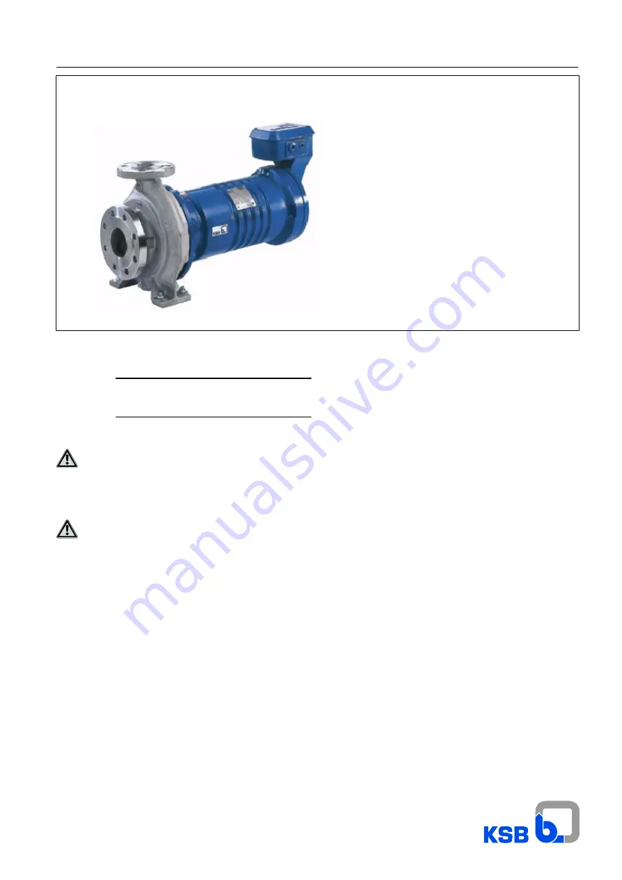
Secochem-Ex

Original operating instructions

2939.8/10-EN

Explosion-proof Standardized

Chemical Pump

with canned motor

Connection dimensions to EN 22 858/ISO 2858

Explosion protection as per directive 94/9/EC

Order No.:

Type series:

These operating instructions contain fundamental

information and precautionary notes. Please read

the manual thoroughly prior to installation of unit,

electrical connection and commissioning. It is imperative

to comply with all other operating instructions referring to

components of individual units.

This manual shall always be kept close to the unit’s

location of operation or directly on the pump set.

Summary of Contents for Secochem-Ex

Page 1: ...No Type series These operating instructions contain fundamental information and precautionary notes Please read the manual thoroughly prior to installation of unit electrical connection and commissioning It is imperative to comply with all other operating instructions referring to components of individual units This manual shall always be kept close to the unit s location of operation or directly ...

Page 2: ...ections 12 5 4 Final check 12 Page 5 5 Electrical connection 12 5 5 1 Terminal box 12 5 5 2 Connecting the power cable 13 5 5 3 Connecting the control cables 13 5 5 4 Monitoring equipment 13 5 5 5 Potential equalisation 13 5 6 Pump operation with frequency inverter 13 6 Commissioning start up shutdown 14 6 1 Commissioning 14 6 1 1 Priming the pump 14 6 1 2 Checking the direction of rotation 15 6 1...

Page 3: ...Marking 2 10 1 6 Marking of instructions in the manual 2 1 4 Measures to be taken for prolonged shutdown 6 3 2 16 Section Page Minimum maximum flow 6 2 5 16 Monitoring equipment 5 5 4 13 Motor unit supplied as spare part 9 7 36 Motors DE 112 9 2 26 Motors DE 160 9 3 28 Motors DE 200 9 4 30 Motors DE 90 9 1 24 Noise characteristics 4 3 6 9 Non compliance with safety instructions 2 3 4 Operating lim...

Page 4: ... in this chapter on Safety be complied with but also the safety instructions outlined under specific headings particularly if the pump unit is operated in hazardous areas see section 2 10 2 1 Marking of instructions in the manual The safety instructions contained in this manual whose non observance might cause hazards to persons are specially marked with the symbol safety sign in accordance with D...

Page 5: ... may affect explosion protection and are only permitted after consultation with the manufacturer The actual dimensions of the flameproof joints are not necessarily identical with those stipulated in EN 60079 1 Tables 1 and 2 Repair work at the flameproof joints must only be performed in accordance with the manufacturer s instructions Repair to the values in tables 1 and 2 of EN 60079 1 is not perm...

Page 6: ...DE90 2 1 1 in combination with temperature class T6 for this combination motor overload protection by means of a motor protection switch is mandatory When reaching the temperature limit stipulated for compliance with the temperature class the canned motor must be cut out by means of an approved tripping unit to Directive 94 9 EC connected to the measuring points provided The following measuring po...

Page 7: ... manufacturer b Ambient temperature for motor DIN EN 60079 0 stipulates an ambient temperature for the motor between 20 _C and 40 _C 2 10 7 Technical design Proper potential equalization between the pump unit and the foundation must be provided for 2 10 8 Maintenance Only a pump unit which is properly serviced and maintained in a perfect technical condition will give safe and reliable operation Re...

Page 8: ... Discharge nozzle DN Nominal impeller dia in mm Rated motor power in kW rounded off to full kW Number of motor poles Explosion proof motor Additional code H heatable version Materials see data sheet Motor Complete motor designation Motor code Complete motor designation code 12 DE 90 2 1 1 22 DE 90 2 2 2 42 DE 112 2 4 52 DE 112 2 5 5 72 DE 132 2 7 5 112 DE 132 2 11 152 DE 132 2 15 222 DE 160 2 22 3...

Page 9: ...2858 For handling combustible media the pump casing must be made of ductile material with a maximum magnesium content of 7 5 see EN 13463 1 This is a standard feature in all KSB supplies 4 3 3 Impeller type Closed radial impeller with multiple vanes Axial thrust is balanced by back vanes 4 3 4 Drive Explosion proof three phase asynchronous canned motor type of protection IP 55 EN 60034 5 Explosion...

Page 10: ... the above diagram Suction nozzle Discharge nozzle Fig 4 Pump sizes Forces Moments Pump sizes Suction nozzle in N Discharge nozzle in N Suction nozzle in Nm Discharge nozzle in Nm Fx Fy Fz Fres Fx FyTens FyCompr Fz Fres Mx My Mz Mx My Mz 25 160 200 1050 700 850 1100 500 350 650 450 700 550 450 300 400 300 200 32 160 200 250 1350 900 1100 1400 700 450 850 550 900 700 550 350 450 350 250 40 160 200 ...

Page 11: ...ts are not included in KSB s scope of supply The pump must be installed in horizontal position Remove the covers from the suction and discharge nozzle For low noise operation contact KSB to check whether the pump set can be installed on anti vibration mounts On request the pump set can also be installed in vertical position i e with the motor below in accordance with the order specific general arr...

Page 12: ...connections are required for proper functioning of the pump and are therefore of vital importance 5 4 Final check Re check the alignment and connections as described in sections 5 2 and 5 3 5 5 Electrical connection The mains data must match the voltage and frequency data indicated on the name plate The motors shall be connected as shown in the wiring diagram in the terminal box They are designed ...

Page 13: ...ing unit and approval of the tripping unit for use with PTC resistors for thermal monitoring of explosion proof electrical equipment The tripping unit is not explosion proof and therefore has to be installed outside the hazardous area 5 5 4 Monitoring equipment For installation and commissioning of the following monitoring equipment PTC monitoring monitoring of rotor space temperature monitoring o...

Page 14: ...If for handling specific media barrier liquid is to be fed via connection 10 E the pump set must be filled with barrier liquid through this connection for 5 minutes beforehand The shut off valve in the discharge line must be open the shut off valve in the suction line must be closed while this is done Fig 13Pump set connections After filling has been completed turn off the barrier liquid feed and ...

Page 15: ...n Only after the pump has reached full rotational speed shall the shut off valve in the discharge line be opened further and adjusted to comply with the duty point Check the direction of rotation if necessary cf 6 1 2 6 1 6 Shutdown Close the shut off valve in the discharge line If the discharge line is equipped with a non return or check valve the shut off element may remain open if there is back...

Page 16: ...lastic caps or similar Do not fill the pump with preservative 6 4 Returning to service after storage Before returning the pump to service carry out all checks and maintenance work specified in sections 7 1 and 7 2 In addition the instructions laid down in the sections on Installation at site 5 and Commissioning 6 must be observed Immediately following completion of the work all safety relevant and...

Page 17: ...n side for a few minutes Assess the condition of the drained liquid with a view to the safety regulations governing the application in question concentration colour smell etc The pumped product is largely removed from the pump in this way Refer to the liquid contents of the drive section given in table 7 3 for orientation Liquid content of the drive section rotor space Motor size DE Content litres...

Page 18: ...efully out of the rotor space Motors DE 160 and 200 Pull off cup springs 950 23 and thrust bearing 314 01 Remove socket head cap screws 914 07 Use jacking thread to pull bearing ring carrier 391 01 out of casing cover 161 Undo hex nuts 920 04 and lift off casing cover 161 Remove U ring 411 87 Pull rotor 818 carefully out of the rotor space General Do not tilt the rotor when pulling it out to preve...

Page 19: ...g sleeve 529 06 in the conical seat then tighten socket head cap screw 914 80 with the torque given in table 7 5 3 Warning Left hand thread Push thrust bearing 314 02 and bearing sleeve 529 21 onto the pump side shaft end until it will not go any further Motors DE 160 and 200 For fitting the motor side bearing sleeve of the rotor slip the components in the correct sequence of taper lock ring 515 2...

Page 20: ...e shaft collar until the thrust bearing ring rests against the bearing bush Cup springs 950 23 must be mounted pointing in the same direction The highest point of the cup spring pack is at the inside diameter and must point towards the impeller side 3 Fastening the impeller Place key 940 01 into the shaft keyway slip on impeller 230 and disc 550 87 and screw on shaft nut 920 95 Use a torque wrench...

Page 21: ...ncept for spare parts and after sales service Consequently the manufacturer will always have replacement drives on stock in order to restore the pump set s availability in the plant as quickly as possible According to the new service concept the pump drive shall not be repaired on the operator s premises except when replacing spare parts Depending on the number of pump sets installed the operator ...

Page 22: ...ency inverter operation not in frequency inverter operation On frequency inverter increase voltage frequency within the permissible range Check voltage Wear of internal pump parts Replace worn components by new ones Pump back pressure is lower than specified in the pur chase order Adjust duty point accurately In the case of persistent overloading turn down impeller 2 Density or viscosity of the fl...

Page 23: ...Secochem Ex 23 ...

Page 24: ...9 Lists of components and general assembly drawings 9 1 Motors DE 90 motor sizes 12 and 22 flameproof joint Secochem Ex 24 ...

Page 25: ...310 11 Plain bearing motor end comprising taper lock ring 515 23 24 bearing sleeve 529 06 socket head cap screw 914 80 cup spring 950 11 382 Bearing carrier with bearing bush gasket 411 91 screwed plug 903 91 nut 920 36 515 04 Taper lock ring 80 1 Motor unit 2 with O ring 412 21 22 71 cover 812 support stator motor housing can stud 902 04 socket head cap screw 914 38 57 84 hex nut 920 04 818 Rotor...

Page 26: ...9 2 Motors DE 112 motor sizes 42 and 52 and DE 132 motor sizes 72 112 and 152 flameproof joint Secochem Ex 26 ...

Page 27: ...bearing sleeve 529 06 socket head cap screw 914 80 cup spring 950 11 344 Bearing bracket lantern with bearing bush joint ring 411 16 screwed plug 903 16 382 Bearing carrier with bearing bush gasket 411 91 screwed plug 903 91 nut 920 36 515 04 Taper lock ring 80 1 Motor unit 2 with supporting sleeve stator motor housing can O ring 412 21 22 71 cover 812 stud 902 04 socket head cap screw 914 38 57 8...

Page 28: ...9 3 Motors DE 160 motor sizes 222 and 302 flameproof joint Secochem Ex 28 ...

Page 29: ...comprising taper lock ring 515 23 24 bearing sleeve 529 06 hex nut 920 80 cup spring 950 11 382 Bearing carrier with bearing bush gasket 411 91 screwed plug 903 91 nut 920 36 391 01 Bearing ring carrier with bearing bush socket head cap screw 914 07 80 1 Motor unit 2 with O ring 412 21 22 71 cover 812 support stator motor housing can stud 902 04 socket head cap screw 914 38 57 84 hex nut 920 04 81...

Page 30: ...9 4 Motors DE 200 motor sizes 402 and 552 flameproof joint Secochem Ex 30 ...

Page 31: ...omprising taper lock ring 515 23 24 bearing sleeve 529 06 hex nut 920 80 cup spring 950 11 382 Bearing carrier with bearing bush gasket 411 91 screwed plug 903 91 nut 920 36 391 01 Bearing ring carrier with bearing bush socket head cap screw 914 07 80 1 Motor unit 2 with O ring 412 21 22 71 cover 812 support stator motor housing can stud 902 04 socket head cap screw 914 38 57 84 hex nut 920 04 818...

Page 32: ...9 5 Back pull out unit with motors DE 90 motor sizes 12 and 22 flameproof joint Secochem Ex 32 ...

Page 33: ...carrier with bearing bush gasket 411 91 screwed plug 903 91 nut 920 36 515 04 Taper lock ring 80 1 Motor unit 2 with O ring 412 21 22 71 cover 812 support stator motor housing can stud 902 04 socket head cap screw 914 38 57 84 hex nut 920 04 818 Rotor with key 940 01 833 Terminal box comprising gasket 400 81 O ring 412 80 base of terminal box 81 36 terminal box cover 81 22 socket head cap screw 91...

Page 34: ...9 6 Back pull out unit with motors DE 112 motor sizes 42 and 52 and DE 132 motor sizes 72 112 and 152 flameproof joint Secochem Ex 34 ...

Page 35: ...screwed plug 903 16 382 Bearing carrier with bearing bush gasket 411 91 screwed plug 903 91 nut 920 36 515 04 Taper lock ring 80 1 Motor unit 2 with supporting sleeve stator motor housing can O ring 412 21 22 71 cover 812 stud 902 04 socket head cap screw 914 38 57 84 nut 920 04 818 Rotor with bush 540 01 key 940 01 833 Terminal box comprising gasket 400 81 O ring 412 80 base of terminal box 81 36...

Page 36: ...Motor unit with O ring 412 21 22 71 cover 812 support stator motor housing can stud 902 04 socket head cap screw 914 38 57 84 hex nut 920 04 833 Terminal box comprising gasket 400 81 O ring 412 80 base of terminal box 81 36 terminal box cover 81 22 socket head cap screw 914 81 834 Sealed terminal gland with O ring 412 81 disc 550 81 socket head cap screw 914 85 Transport lock cover 160 gasket 400 ...

Page 37: ... 1 EN 60034 5 A1 EN 60079 0 EN 60079 1 EN 60079 7 EN 13463 1 EN 13463 5 EN 1127 1 In compliance with Directive 94 9 EC the pump set is marked as follows II 2 G c TX Pump II 2 G Ex de IIC T6 T5 T4 or T3 Motor The EC Type Test Certificate PTB99ATEX1133 is available for the integrated motor of type DE 90 The manufacturer s quality assurance system is monitored by 0044 TÜV Nord CERT GmbH Germany Perso...

Page 38: ...isposal We hereby declare that this product is free from hazardous chemicals biological or radioactive substances On seal less pumps the rotor has been removed from the pump for cleaning No special safety precautions are required for further handling The following safety precautions are required for flushing fluids fluid residues and disposal We confirm that the above data and information are corr...

Page 39: ...azards arising from components in contact with the fluid handled Discharge line Leitung die am Druckstutzen angeschlossen ist Motor unit Motor unit supplied as spare part Stator with motor housing can and electrical connection elements for stator without rotor impeller and main bearing Pool of pumps Pumps which are purchased and stored independently of their later use Pump Machine without drive ad...

Page 40: ...ng instructions Secochem Ex Original operating instructions KSB Aktiengesellschaft All rights reserved Contents provided herein must neither be distributed copied reproduced processed for any other purpose nor otherwise transmitted to a third party without KSB s express written consent Subject to technical modification without prior notice E KSB Aktiengesellschaft Frankenthal 19 06 2013 ...

Reviews: