


5 Reassembly
17 of 44
EA-C
WARNING
Sudden start-up of the continuous-action actuator with power back-up unit after
disconnection from the mains.
Crushing of hands!
▷
Disconnect the equipment from the power supply.
▷
Secure against unauthorised start-up.
CAUTION
Pressing down the actuator cover with force
Damage to components!
▷
Turn the actuator cover gently to and fro until you can feel it lock in position.
NOTE
The terminal box has terminals for connecting solid and flexible electrical cables
with cross-sections from 0.14 mm
2
to 2.5 mm
2
as well as a PE terminal on the
housing.
Depending on the actuator, the terminal box is located behind the terminal box
cover or under the actuator cover.
Terminal box behind the terminal box cover (on continuous-action actuators and
24 V 3-point actuators)
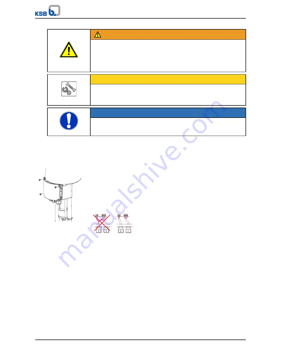
Fig. 7:
Undo the screws.
1. Undo and store the terminal box screws.
2. Remove the terminal box cover.
3. Unscrew the cable gland.
4. Choose the supply voltage and control signals in accordance with the data on
the name plate.
5. Connect the cables for power supply and control to the terminals as shown in
the wiring diagram. (
ð
Section 9.3, Page 32)
ð
Use separate power cables for this purpose.
Fig. 8:
Power cable and control cable
6. Mechanically secure the power cable and the control cable before the terminals
against loosening.
7. Fasten the cable gland.
8. Fasten the terminal box cover with the screws.
ð
Only tighten the screws until resistance can be felt.
Summary of Contents for EA-C
Page 43: ......