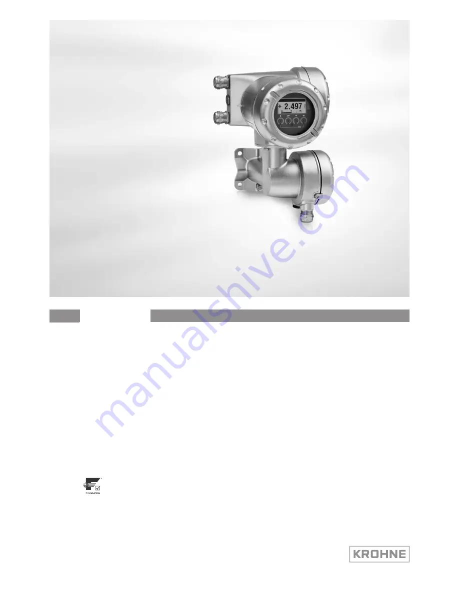
background image

Signal converter for ultrasonic flowmeters

Description of Foundation Fieldbus interface

Description of Foundation Fieldbus interface

Description of Foundation Fieldbus interface

Description of Foundation Fieldbus interface

Electronic Revision: ER 3.0.1_

UFC 400

UFC 400

UFC 400

UFC 400

Supplementary Instructions

Supplementary Instructions

Supplementary Instructions

Supplementary Instructions

© KROHNE 12/2015 - 4002813702 - AD FF UFC 400 R02 en

The documentation is only complete when used in combination with the relevant 
documentation for the flow sensor.

Summary of Contents for UFC 400

Page 1: ...e Description of Foundation Fieldbus interface Electronic Revision ER 3 0 1_ UFC 400 UFC 400 UFC 400 UFC 400 Supplementary Instructions Supplementary Instructions Supplementary Instructions Supplement...

Page 2: ...e types 5 3 2 Shielding and grounding 5 3 3 Electrical connection of FOUNDATION Fieldbus 6 3 4 Topology of FF networks 7 4 Operation 8 4 1 Settable functions 8 4 2 Description of the FF block system 9...

Page 3: ...nt of actual volume flow mass flow flow speed velocity of sound gain SNR and diagnosis value Exclusively for bi directional measuring of conductive and or non conductive fluids in closed completely fi...

Page 4: ...anced Resource Block RB 1 x Customer Flow Transducer Block FLOWTB 1 x Customer Diagnose Transducer Block DIAGTB 4 x Analog Input Block AI 2 x Integrator Block IT 1 x Proportional Integral Derivate Blo...

Page 5: ...n hazardous location along the entire Fieldbus installation is strongly recommended Multiple grounding of the shield is of advantage In explosion proof systems the shielding must at least be connected...

Page 6: ...e wiring between the device and the FOUNDATION Fieldbus cable is independant of polarity The signal converter FOUNDATION Fieldbus interface will operate only if the additional power supply for the dev...

Page 7: ...nnect and disconnect the devices without interrupting the bus or the communication 1 HSE network 2 H1 bus 3 Intrisically safe explosive area B1 B2 Bridge coupling element for H1 bus and HSE network D1...

Page 8: ...T Not available for Foundation Fieldbus devices C5 4 2 meas page In case of Foundation Fieldbus device the second measurement page is meant to check the output values of the different function blocks...

Page 9: ...e within a user application In this block scheme a distinction is made between the Resource Block Transducer Block and Function Block 4 3 Used abbreviations 1 Resource Block RB 2 Transducer Block TB 3...

Page 10: ...figuration Error detected in link configuration Simulation Active Simulation enabled in this block Local Override Output tracking of faultstate active Device Fault State Device faultstate set Device M...

Page 11: ...es of the alarms associated with the function block Current R The active status of each alarm Uninitialized Setting Discrete Alarm Block Alarm Fail Alarm Off Spec Alarm Maintenance Alarm Check Alarm U...

Page 12: ...ng Uninitialized Off Clear CONFIRM_TIME CONFIRM_TIME CONFIRM_TIME CONFIRM_TIME Confirm Time Confirm Time Confirm Time Confirm Time R W The minimum time between retries of alert reports 640000 Setting...

Page 13: ...Sensor 24 C Process 25 C Configuration 26 C Electronics 27 C Sensor 28 F Process 29 F Configuration 30 F Electronics 31 F Sensor FD_CHECK_ALM FD_CHECK_ALM FD_CHECK_ALM FD_CHECK_ALM Check Alarm This p...

Page 14: ...iority R W This parameter allows the user to specify the priority of this alarm category 0 Setting 0 15 FD_FAIL_ACTIVE FD_FAIL_ACTIVE FD_FAIL_ACTIVE FD_FAIL_ACTIVE Fail Active R This parameter reflect...

Page 15: ...01 Electronics Operation Info 08 Electronics Power Fail 10 Configuration Totaliser 11 Process Signal Unreliable 12 Process Signal Lost 13 Process Empty Pipe 14 Electronics IO Connection 15 Process Cur...

Page 16: ...ed Setting 00 Reserved FD_EXTENDED_ FD_EXTENDED_ FD_EXTENDED_ FD_EXTENDED_ ACTIVE_8 ACTIVE_8 ACTIVE_8 ACTIVE_8 FD_EXTENDED_ ACTIVE_8 R An optional parameter to allow the user finer detail on condition...

Page 17: ...30 Backup 2 Data Faulty 31 Backup 1 Data Faulty FD_EXTENDED_ FD_EXTENDED_ FD_EXTENDED_ FD_EXTENDED_ ACTIVE_18 ACTIVE_18 ACTIVE_18 ACTIVE_18 FD_EXTENDED_ ACTIVE_18 R An optional parameter to allow the...

Page 18: ...low the user finer detail on conditions causing an active condition in the FD_ _ACTIVE parameter Uninitialized Setting 00 Reserved FD_EXTENDED_ FD_EXTENDED_ FD_EXTENDED_ FD_EXTENDED_ ACTIVE_28 ACTIVE_...

Page 19: ...TENDED_MAP_ FD_EXTENDED_MAP_ FD_EXTENDED_MAP_ FD_EXTENDED_MAP_ 5 5 5 5 FD_EXTENDED_MAP_ 5 R An optional parameter to allow the user finer control on enabling conditions contributing to the conditions...

Page 20: ...00 Reserved FD_EXTENDED_MAP_ FD_EXTENDED_MAP_ FD_EXTENDED_MAP_ FD_EXTENDED_MAP_ 17 17 17 17 FD_EXTENDED_MAP_ 17 R W Field Diagnostics of M Configuration Uninitialized Setting 30 Backup 2 Data Faulty...

Page 21: ...isplay Config 26 Process Input Config 30 DM Configuration 31 BM Configuration FD_EXTENDED_MAP_ FD_EXTENDED_MAP_ FD_EXTENDED_MAP_ FD_EXTENDED_MAP_ 30 30 30 30 FD_EXTENDED_MAP_ 30 R W Field Diagnostics...

Page 22: ...6 17 18 19 Setting 00 Check 01 Electronics Operation Info 08 Electronics Power Fail 10 Configuration Totaliser 11 Process Signal Unreliable 12 Process Signal Lost 13 Process Empty Pipe 14 Electronics...

Page 23: ...ting Uninitialized Acknowledged Unacknowledged Alarm State R A discrete enumeration which gives an indication of whether the alert is active and whether it has been reported Uninitialized Setting Unin...

Page 24: ...numerated action what should be done to alleviate the condition or conditions Uninitialized Setting 0 Not Initialized 1 No Action Required 2 Remove Simulate Jumper 1 01 00 Keys can be used 60 sec afte...

Page 25: ...simulation mode 1 25 31 For normal operation turn off simulation mode 1 26 00 reserved 1 27 00 reserved 1 28 00 reserved 1 29 02 Check IO B configuration or reset to factory configuration 1 29 03 Che...

Page 26: ...M Configuration 18 M Electronics 19 M Sensor 20 S Process 21 S Configuration 22 S Electronics 23 S Sensor 24 C Process 25 C Configuration 26 C Electronics 27 C Sensor 28 F Process 29 F Configuration 3...

Page 27: ...rer identification number used by an interface device to locate the DD file for the resource KROHNE Setting KROHNE MAX_NOTIFY MAX_NOTIFY MAX_NOTIFY MAX_NOTIFY Maximum Notify R Maximum number of unconf...

Page 28: ...detected that is unreported The time stamp value will be maintained constant until alert confirmation has been received even if another change of state occurs Uninitialized Setting MM DD YY Month Day...

Page 29: ...WRITE_PRI WRITE_PRI Write Priority R Priority of the alarm generated by clearing the write lock 0 Setting 0 15 DIAGNOSIS DIAGNOSIS DIAGNOSIS DIAGNOSIS Diagnosis R Detailed diagnosis of the device MEM...

Page 30: ...ed parameters Production Setting Concentration bit 5 6 not use User Service level Production Custody Transfer Write Lock SERIAL_NUMBER SERIAL_NUMBER SERIAL_NUMBER SERIAL_NUMBER Serial Number R Device...

Page 31: ...for sorting alarms etc 0 Setting 1 255 BLOCK_ERR BLOCK_ERR BLOCK_ERR BLOCK_ERR Block Error R This parameter reflects the error status associated with the hardware or software components associated wit...

Page 32: ...of the block blanks Setting 32 digits ACK_OPTION ACK_OPTION ACK_OPTION ACK_OPTION Acknowledge Option R W Selection of whether alarms associated with the function block will be automatically acknowledg...

Page 33: ...g Uninitialized Clear reported Clear not reported Active reported Active not reported Time Stamp R The time when evaluation of the block was started and a change in alarm event state was detected that...

Page 34: ...or High Alarm and its associated time stamp Settings of 5 subelements see in the following part HI_HI_ALM HI_HI_ALM HI_HI_ALM HI_HI_ALM High High Alarm Mix The status for High High Alarm and its assoc...

Page 35: ...lements see in the following part LO_LO_ALM LO_LO_ALM LO_LO_ALM LO_LO_ALM Low Low Alarm Low Low Alarm Low Low Alarm Low Low Alarm The status for Low Low Alarm and its associated time stamp Settings of...

Page 36: ...R W A numerical quantity entered by a user or calculated by the algorithm OUT_SCALE OUT_SCALE OUT_SCALE OUT_SCALE Output Scale R W The high and low scale values engineering units code and number of di...

Page 37: ...initialized Acknowledged Unacknowledged Update State R A discrete enumeration which gives an indication of whether the alert has been reported Uninitialized Setting Uninitialized Reported Not Reported...

Page 38: ...st s Ston s st min Ston min st h Ston h st d Ston d lt s LTon s lt min Lton min lt h LTon h lt d LTon d MLB H Volume flow units Volume flow units Volume flow units Volume flow units m s m min m h m d...

Page 39: ...d Lost Static Data Static parameters cannot be recovered Lost NV Data Non volatile parameters cannot be recovered Readback Check Failure detected in READBACK Maintenance Needed Device NEEDS maintenanc...

Page 40: ...her the alert is active and whether it has been reported Uninitialized Setting Uninitialized Clear reported Clear not reported Active reported Active not reported Time Stamp R The time when evaluation...

Page 41: ...Y_VALUE_ TYPE TYPE TYPE TYPE Primary Value Type R The type of measurement represented by the primary value For example mass flow absolute pressure differential temperature Volumetric flow PRIMARY_VALU...

Page 42: ...nits code index for the engineering unit descriptor for the associated block value m s Settings m s mm s m h km h in s ft s yd s in min ft min yd min in h ft h yd h DECIMAL Decimal Point R The number...

Page 43: ...9 1 00 kg L Settings 0 1 5 0 kg L DYN_VISCOSITY DYN_VISCOSITY DYN_VISCOSITY DYN_VISCOSITY Dynamic viscosity R W Dynamic viscosity of fluid Fct C1 7 2 1 0 cP Settings 0 1 5000 0 cP ERROR_LIMIT ERROR_L...

Page 44: ...nch 7000 700 mm 28 inch 7500 750 mm 30 inch 8000 800 mm 32 inch 8500 850 mm 34 inch 9000 900 mm 36 inch 9500 950 mm 38 inch 10000 1000 mm 40 inch 10500 1050 mm 42 inch 11000 1100 mm 44 inch 11500 1150...

Page 45: ...of the point The engineering units must match the units selected in the parameter XD_SCALE of the Analog Input Block that reads the channel with this value EU_100 max value R The engineering unit valu...

Page 46: ...ING TRACKING Tracking R W Tracking Fct D1 9 Normal Settings Normal Fast TRANSDUCER_ TRANSDUCER_ TRANSDUCER_ TRANSDUCER_ DIRECTORY DIRECTORY DIRECTORY DIRECTORY Transducer Directory Entry A directory t...

Page 47: ...cifications in section 4 7 Block Alarm Subcodes Uninitialized Settings 16 Unspecified error 17 General error 18 Calibration error 19 Configuration error 20 Electronics Failure 21 Mechanical Failure 22...

Page 48: ...ted Lost Static Data Static parameters cannot be recovered Lost NV Data Non volatile parameters cannot be recovered Readback Check Failure detected in READBACK Maintenance Needed Device NEEDS maintena...

Page 49: ...her the alert is active and whether it has been reported Uninitialized Setting Uninitialized Clear reported Clear not reported Active reported Active not reported Time Stamp R The time when evaluation...

Page 50: ...n a Transducer Block PRIMARY_VALUE_ PRIMARY_VALUE_ PRIMARY_VALUE_ PRIMARY_VALUE_ 201 201 201 201 Velocity of Sound The measured velocity of sound value and status available to the Function Block STATU...

Page 51: ...ction Block STATUS Status R Digital transducers unlike their analogue versions can detect faults that make the measurement bad or prevent the actuator from responding This additional valuable informat...

Page 52: ...ON C Number Production R C Number of production this number identifies the type of electronics can be found on the converter assembly sticker as well Fct B3 3 C5 1 2 DEVICE_SN DEVICE_SN DEVICE_SN DEVI...

Page 53: ...r of paths 3 none velocity of sound 1 velocity of sound 2 velocity of sound 3 flow speed 1 flow speed 2 flow speed 3 SELECTOR_ SELECTOR_ SELECTOR_ SELECTOR_ DIAGNOSIS_2 DIAGNOSIS_2 DIAGNOSIS_2 DIAGNOS...

Page 54: ...TRANSDUCER_ DIRECTORY DIRECTORY DIRECTORY DIRECTORY Transducer Directory Entry A directory that specifies the number and starting indices of the data collections in the transducer block 0 TRANSDUCER_...

Page 55: ...cific error active Block Configuration Error detected in block configuration Simulation Active Simulation enabled in this block Local Override Output tracking of faultstate active Device Fault State D...

Page 56: ...ed status is cleared by the alert reporting task another block alert may be reported without clearing the Active status if the subcode has changed Unacknowledged R W A discrete enumeration which is se...

Page 57: ...in the case of Local may turn on an item of the Grant attribute Program Tune Alarm or Local Uninitialized Setting Program Tune Alarm Local Deny R W The Denied attribute is provided for use by a monito...

Page 58: ...t manual reset must be preceded by a reset confirmation by the control system Generate reset event in case of reset automatic or manual an event notification will be sent to the control system This fu...

Page 59: ...sitive or 0 PULSE_VAL1 PULSE_VAL1 PULSE_VAL1 PULSE_VAL1 Pulse Value 1 Pulse Value 1 Pulse Value 1 Pulse Value 1 R W Determines the mass volume or energy per pulse 0 0 Setting Positive or 0 PULSE_VAL2...

Page 60: ...1 Time Unit 1 Time Unit 1 Time Unit 1 Time Unit 1 R W Converts the rate time units in seconds Uninitialized Setting 1 seconds 2 minutes 3 hour 4 days TIME_UNIT2 TIME_UNIT2 TIME_UNIT2 TIME_UNIT2 Time U...

Page 61: ...ing MM DD YY Month Day Year HH MM SS Hour Minute Second Static Revision R The static revision of the block whose static parameter was changed and is being reported It is possible for the present value...

Page 62: ...e Maintenance Device needs maintenance soon Input Failure Process variable has bad status Output Failure Failure detected in output hardware Memory Failure Memory error detected Lost Static Data Stati...

Page 63: ...teresis Alarm Hysteresis Alarm Hysteresis Alarm Hysteresis R W Amount the PV must return within the alarm limits before the alarm condition clears Alarm hysteresis expressed as a percent of the span o...

Page 64: ...R W The block alarm is used for all configuration hardware connection failure or system problems in the block The cause of the alert is entered in the subcode field The first alert to become active w...

Page 65: ...power failure OutOfService Block actual mode is Out of Service Value R The value of the associated parameter at the time the alert was detected 0 Setting 0 255 BYPASS BYPASS BYPASS BYPASS Bypass Bypas...

Page 66: ...d as the working SP or the PV normally BKCAL_OUT is the working SP Restrict SP to limits in Cas and RCas If this option is selected the setpoint will be restricted to the setpoint absolute and rate li...

Page 67: ...arm State R A discrete enumeration which gives an indication of whether the alert is active and whether it has been reported Uninitialized Setting Uninitialized Clear reported Alarm not active and rep...

Page 68: ...Options for controlling access of host computers and local control panels to operating tuning and alarm parameters of the block Grant R W Depending on the philosophy of the plant the operator or a hi...

Page 69: ...its associated time stamp Unacknowledged R W A discrete enumeration which is set to Unacknowledged when an alarm occurs and set to Acknowledged by a write from a human interface device or other entit...

Page 70: ...m event has been noticed Uninitialized Setting Uninitialized Acknowledged Unacknowledged Alarm State R A discrete enumeration which gives an indication of whether the alert is active and whether it ha...

Page 71: ...Low Low Limit Low Low Limit Low Low Limit R W The setting for Low Low Alarm in engineering units INF LO_LO_PRI LO_LO_PRI LO_LO_PRI LO_LO_PRI Low Low Priority Low Low Priority Low Low Priority Low Low...

Page 72: ...ring unit descriptor for the associated block value Uninitialized Setting All units are possible Decimal Point R W The number of digits to the right of the decimal point which should be used by an int...

Page 73: ...ined mode SP SP SP SP Setpoint Setpoint Setpoint Setpoint R W Setpoint 0 Status Status of SP Value Value of SP SP_HI_LIM SP_HI_LIM SP_HI_LIM SP_HI_LIM Setpoint High Limit Setpoint High Limit Setpoint...

Page 74: ...at 100 R W The engineering unit value which represents the upper end of range of the associated block parameter 100 EU at 0 R W The engineering unit value which represents the lower end of range of th...

Page 75: ...HH MM SS Hour Minute Second Static Revision R The static revision of the block whose static parameter was changed and is being reported It is possible for the present value of static revision to be gr...

Page 76: ...Services Head Office KROHNE Messtechnik GmbH Ludwig Krohne Str 5 47058 Duisburg Germany Tel 49 203 301 0 Fax 49 203 301 10389 info krohne com KROHNE 12 2015 4002813702 AD FF UFC 400 R02 en Subject to...

Reviews: