11
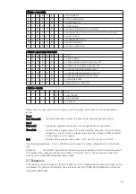
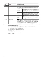
Block Number
Standard-Configuration
(function block output value)
PA039742. GSD
Ident-No. 9742
Default
unit:
1
Mass Flow
AI-FB
kg/s
2
Density
AI-FB
kg/m3
3
Medium Temperature
AI-FB
K
4
Mass Totaliser
Totaliser-FB
kg
All other values of ModeTot are not allowed. Value is ignored; totaliser remains in its last valid
setting.
The standard block configuration may be changed by the customer but using the default set-
tings is highly recommended. If the standard block configuration should be changed by the
customer an acyclic master tool must be used to change the “channel parameter” value of the
block which should be connected to another transducer output value.
2
2..4
4..2
2 P
Prro
offiille
e s
sp
pe
ec
ciiffiic
c G
GS
SD
D ffiille
e:: P
PA
A0
03
39
97
74
42
2.. G
GS
SD
D
The functionality of the profile specific GSD file is limited. This GSD file includes only four
blocks:
S
Se
ettT
To
ott::
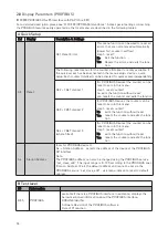
SetTot =0:
Totaliser is totalising.
SetTot =1:
Totaliser will be reset to 0 and stays at 0 until SetTot is switched back again
to 0. If the value of SetTot changes from “1” to “0” the totaliser starts count-
ing from 0.
SetTot =2:
Totaliser is set to the value defined by PresetTot. PresetTot can be written via
a acyclic master (totaliser in block 4 = Slot 4 Index 32; totaliser in block 5 =
Slot 5 Index 32; totaliser in block 6 = Slot 6 Index 32). If the value of SetTot
changes from “2” to “0” the totaliser starts counting from the current value
defined by PresetTot.
SetTot ? 2:
not allowed. Value is ignored; totaliser remains in its last valid setting.
M
Mo
od
de
eT
To
ott::
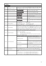
ModeTot = 0
totaliser totalises positive and negative values.
ModeTot = 1
totalises only positive values.
ModeTot = 2
totalises only negative values.
ModeTot = 3
totaliser is stopped, no totalization will be done.
ModeTot = 248 totalises all values as positive (negative values will be multiplied with “-1.0”)
ModeTot = 249 totalises all values as negative (positive values will be multiplied with “-1.0”)
The device has to be switched from “Manufacturer Specific” (full functionality) to “Profile
Specific” (interchangeable basic configuration) by using a master class 2 tool (IDENT_NUM-
BER_SELECTOR: Slot 0, Index 40 change byte value to 0). After this the device has to be pro-
jected by using the PA039742.GSD file.
2
2..4
4..3
3 C
Cyyc
clliic
c d
da
atta
a e
ex
xc
ch
ha
an
ng
ge
e
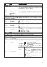
During network configuration the user has to define which function block outputs of the
MFC300 PROFIBUS RS-485 should be transferred cyclically to the master. Network configura-
tion will be done using one of the GSD files described above. The order of transmission of a
function block always remains the same even if a function block is defined as an “Empty” block
(in this case, no function block output data will be sent to the master and all function block out-
puts following the “Empty” block will move up one position)
.


