background image

BM 70 M 

31

8.2 

Function of the keys 

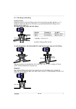
The three keys have the following functions: 

 (Cursor key): 

- selects the configuration menu 
- branches the menu to the next lower level, 
- moves the cursor* to the right to the next column. 

 (Select key): 

- branches the menu to the next digit in the same 
level,
- changes the content (digit, character) at the cursor* 
position.

 (Enter key): 

- selects the error memory, 
- branches the menu to the next higher level, 
- stores newly entered parameters, 
- executes displayed functions. 

* The cursor position is signalled by flashing of the character or selected point at the appropriate 
place.

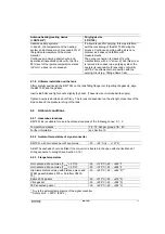
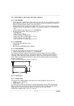
To start operator control: 

Measuring mode 


Operator control mode 

                                            627 


                                 Fct. 1.0 

                                             cm 


                        OPERATION 

Note:

When "YES" is set under Fct. 3.4.2 and ENTRY CODE "CodE1 -------" appears 
in the display, the 

 key must be pressed 

The 9-keystroke Entry Code1 must then be entered: 
Factory setting: 

→→→↑↑↑↵↵↵

 (each keystroke confirmed in the display by "*".) 

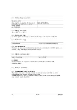
To terminate operator control: 

Press key 

 repeatedly until one of the following menus is displayed. 

Fct. 1.0 OPERATION, Fct. 2.0 TEST or Fct. 3.0 INSTALL. 

Measuring mode 

 Press key...... 

Operator control mode 

                                     Fct. 3.0 


                                    INSTALL 


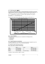
STORE                         YES 

New parameters not to be 
stored

Press

 key to display 

"STORE.NO". Measuring mode 
continued with the "old" 
parameters after pressing the 

key; the "START" message is 
shown until a measured value is 
determined.
If instead you wish to return to 
Configuration, press the 

 key first 

until "RETURN" is displayed, and 
then the 

 key. 

Store new parameters 

Confirm by pressing the 

NH\

"START" is displayed, and the 
measuring mode is continued with 
the new parameters. 

Summary of Contents for BM 70 M Series

Page 1: ...x BM 70 Mi EEx KROHNE 08 2002 7 10027 21 00 GR Variable area flowmeters Vortex flowmeters Flow controllers Electromagnetic flowmeters Ultrasonic flowmeters Mass flowmeters Level measuring instruments...

Page 2: ...nsient recovery time 14 5 6 Long term drift 14 5 7 Effect of ambient temperature 14 6 Operating conditions 14 6 1 Installation conditions 15 6 1 1 Transmission angle 15 6 1 2 Recommendations for posit...

Page 3: ...ctrum 51 8 6 13 Time constant and tracking speed 54 8 6 14 Multiple reflections and block distance detection 54 8 6 15 Tank bottom tracing system 55 8 6 16 Tank type movement of product surface 56 8 6...

Page 4: ...pplied Depending on the version ordered we supply the following Signal converter bolted to waveguide window and antenna Optional antenna extension sunshade with fastening material in each case Report...

Page 5: ...The difference is directly proportional to the distance i e a large frequency difference corresponds to a large distance and vice versa The frequency difference is transformed via a Fourier transform...

Page 6: ...low for plausibilities and history The following diagram describes the path of internal signal processing After automatic gain control the measuring signal is filtered digitized and converted into a f...

Page 7: ...tem 3 Input 3 1 Measured variable distance level volume reflection The primary measured variable is the distance between a reference point as standard tank mounting flange and a reflecting surface e g...

Page 8: ...ART protocol together with switching output and digital input 4 2 4 4 Ex i current output HART intrinsically safe passive HART protocol optionally with intrinsically safe switching output 4 3 4 4 Curr...

Page 9: ...nd switching output Current 4 20 mA without or with error message 2 mA and 22 mA Accuracy linearity 0 05 rel 20 mA at T 20 C 100ohm load impedance and nominal operating voltage Temperature drift 100 p...

Page 10: ...ondition Operating data 6 30 V ILow 110 mA ULow 2V IHigh 900 A U 30V and IHigh 200 A U 8V Ex i safety limits Signal circuit in type of protection Intrinsic Safety EEx ia IIC IIB or EEx ib IIC IIB for...

Page 11: ...2 mA when load 250 Ohm No load voltage 18 V 4 6 Digital interface RS 485 RS 485 is a bus that allows two way Communication half duplex operation with the BM 70 M Level Radar When the computer system s...

Page 12: ...at the last device should be terminated with the typical surge impedance of the cable 120 Ohm To do this inside the BM 70 M see Section 7 7 4 7 Breakdown signal Breakdown information can be called up...

Page 13: ...vate it completely the setting will need to be changed in the Service menu of the BM 70 M 5 Measuring accuracy 5 1 Reference conditions Temperature 20 C 68 F Pressure 1013 mbar abs 14 5 psia Air humid...

Page 14: ...rature effects using reference measurements in liquid tanks it needs to be remembered that liquids generally have a high coefficient of expansion organic liquids typically 0 15 C 6 Operating condition...

Page 15: ...tical in which the power density of the radar waves assumes half the value of the maximum power density half power beam width Antenna Type Diameter mm inches Transmissi on angle Lobe expansion s per m...

Page 16: ...on above internals interference reflections If these recommendations cannot be followed because of the tank geometry please consult KROHNE B Stilling well or Wave Guide A stilling well or Wave Guide m...

Page 17: ...Type 3 140 mm 5 5 223 mm 8 8 Hastelloy 30 mm 1 2 subject to change without notice An antenna extension should be added if the antenna does not project out of the fitting Antenna extensions are availa...

Page 18: ...embled stilling well is necessary abrupt changes in diameter along the pipe should be less than 1 mm 0 04 Surface roughness of the inside of the pipe should not be more than 0 1 mm 0 004 For the BM 70...

Page 19: ...ave Guide is a pipe with an outside diameter of 30 mm 1 18 and an inside diameter of 25 mm 0 98 that is bolted direct to the BM 70 flange system in the same way as an antenna extension It functions li...

Page 20: ...nal converter Standard sizes others on request Dimensions in mm inches 6 1 7 Special options for the flange Antenna heating cooling device DN150 6 Purging device DN100 Double walled antenna for coolin...

Page 21: ...he gasket align the BM 70 M and the gasket Insert stud bolts and tighten nuts slightly by hand These items not included with supply Tighten down stud bolts and nuts firmly The torque is dependent on t...

Page 22: ...The device has been found to withstand the impact test in conformity with EN 61010 Section 8 2 with 0 5 J energy and the drop test to prEN 50178 1994 6 2 9 Vibration endurance limit Type test conditi...

Page 23: ...iquid ammonia liquid hydrogen liquid helium 6 3 4 Product temperature unrestricted The product temperature is not a relevant factor provided the ambient temperature see 6 2 2 and the flange temperatur...

Page 24: ...washing down or cleaning with mechanical aids take special care not to damage either the horn antenna or the bottom Teflon plug at the waveguide window see Section 7 3 Field assembly of the BM 70 M If...

Page 25: ...remove this first see Section 6 1 9 2 Disconnect all cables from the terminals in the terminal compartment see Section 7 6 3 Remove the 4 Allen screws M Allen key size 5 mm and lift off the signal con...

Page 26: ...onality of the BM 70 M Bolt antenna and antenna extension together torque for the 3 stud bolts max 8 Nm 0 8 kpm Do not on any account detach screws H 7 4 Materials of construction Check the materials...

Page 27: ...e limitations due to Ex approval see Part 2 of this installation and operating instructions Responsibility as to suitability rests solely with the user Available materials for internal device seals an...

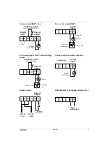
Page 28: ...on see also terminal assignments below and in Sect 9 4 Cable entries 3x M25x1 5 with standard cable gland cable clamping area 9 16 mm Signal cable shielding required for RS 485 line recommended for cu...

Page 29: ...41 Current output Switching output max 100mA 30V DCAC Digital input 82 81 5 28V 4 20mA max 500 32 31 Ex i IS supply unit U max 30V Current output 4 20mA U min 8V Current output Switching output max 11...

Page 30: ...rried out directly at the device If a local display is not featured the PC CAT program see Sect 8 12 must be used to change the parameter setting assuming a communicable interface is provided The avai...

Page 31: ...Note When YES is set under Fct 3 4 2 and ENTRY CODE CodE1 appears in the display the key must be pressed The 9 keystroke Entry Code1 must then be entered Factory setting each keystroke confirmed in t...

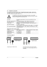
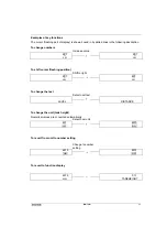
Page 32: ...3 4 4 3 3 1 3 3 7 3 1 1 3 1 8 3 2 1 3 2 5 Directions for using the keys in the menu levels and colum ns The flashing part of the display cursor can be changed Selection of function with the key 1 0 OP...

Page 33: ...627 637 cm cm To shift cursor flashing position Shift to right 637 637 cm cm To change the text Select next text LEVEL DISTANCE To change the unit tank height Numerical values are converted automatica...

Page 34: ...V Options USER UNIT Cubic meter m3 Select unit for conversion value to be displayed volume table 2 0 TEST 2 1 HARDWARE 2 1 1 MASTER Special function Tests the hardware of the master 2 1 2 DISPLAY Spec...

Page 35: ...ered here is also used for all other length inputs 3 1 2 BLOCKDIST Enter 0 10 m tank height 0 50 m To input the block distance The block distance marks the non measurable range below the bottom edge o...

Page 36: ...or display of the conversion value 3 2 4 USER UNIT Text entry 10 ASCII characters ________ Input of freely programmable unit for the conversion table max 10 characters Options NO 3 2 5 ERROR MSG YES Y...

Page 37: ...FOUND deviating options 3 3 6 ADDRESS Enter 0 255 0 Input of the device address for Communication For Fct 3 3 7 PROFIBUS PA or F FOUND deviating input range Options HART MODBUS PROFIBUS PA 3 3 7 PROTO...

Page 38: ...on off Options NO 3 5 6 BD DETECT YES YES Switch the block distance overfill detector on off Options OFF 3 5 7 FUNCT FTB PARTIAL OFF Select function of the tank bottom tracking system 3 5 8 EPSILON R...

Page 39: ...for the switching output Input is dependent on the function of the switching output Default values following a parameter reset use of a new EEPROM not yet described The factory setting for the parame...

Page 40: ...greater than the response threshold 8 5 2 Volume measurement example In order to be able to measure volume with the BM 70 M a conversion table volume table needs to be compiled with the PC CAT program...

Page 41: ...following functions Block distance Fct 3 1 2 Antenna extension Fct 3 1 4 Scaling 4 mA value current output Fct 3 3 3 Scaling 20 mA value current output Fct 3 3 4 Range for partial tank bottom tracing...

Page 42: ...l conversion pairs The values are linearly established interpolated between 2 points Also for the local display an arbitrary max 10 character text Fct 3 2 4 can be defined as a unit under Fct 3 2 4 In...

Page 43: ...64 131 22 ft For BM 70 M max 35m 1377 9 inch 114 8 ft Depending on the version it is also possible to set an upper limit for the tank height The maximum value can be increased by KROHNE Service to up...

Page 44: ...etting possible Fct 3 1 4 ANT EXTENS The length of the supplied antenna extension is factory set here Unit and setting range same as Fct 3 1 1 TANKHEIGHT This setting may only be changed when a longer...

Page 45: ...e see Example 1 below The offset is effective for all distance values local display current output switching output digital information Setting range 10 m 10 m 32 8 ft Default value 0 Fct 3 1 8 TB OFF...

Page 46: ...offset 2 m Reference offset 0 The possible measuring range is Level 2 m to 8 m block distance Example 3 Only a specific part of the level in a very tall tank is to be measured in the example levels 5...

Page 47: ...are displayed in the form of vertical lines in the first line of the display 0 1 segment 100 25 segments Fct 3 2 3 or Fct 1 1 3 UNIT CONV Use this function to select the unit for conversion display m...

Page 48: ...Fct 3 3 1 Setting range and unit for SCALE 4 mA same as for Fct 3 1 1 TANKHEIGHT If a reference or tank bottom offset is set this must be allowed for Setting CONVERSION under Fct 3 3 1 Unit for SCALE...

Page 49: ...rameters and functions of the BM 70 M In addition there is the device description DD for BM 70 M which can be used for universal HART control units such as the HART Communicator or SIPROM The standard...

Page 50: ...1 GB USA English E Spanish Espa ol D German P Portuguese F French S Swedish I Italian Coding desired for entry into setting level Set NO or YES in Fct 3 4 2 ENTRY CODE1 If NO set simply press key WR...

Page 51: ...rferences for automatic determination of the tank height Press key to abort the operation In this case you will need to enter the tank height manually with Fct 3 1 1 8 6 12 Empty spectrum What is an e...

Page 52: ...ctory set is here AVERAGE normal empty spectrum This setting is suitable for most applications possible alternative Recording of the empty spectrum over the full range If the tank cannot be drained ov...

Page 53: ...corded Of advantage in conjunction with difficult agitators for example If the tank is not completely drained the empty tank spectrum can nevertheless still be recorded up to a certain range In this c...

Page 54: ...ld be set as the minimum value Setting ranges 0 01 1 00 m min if Fct 3 1 1 Unit m cm mm 0 03 3 28 ft min if Fct 3 1 1 Unit inch ft Default 0 1 m min BM 70 M See also Sect 8 8 error message NO M VALUE...

Page 55: ...is parameter can also be determined by a KROHNE Service technician from the recording of a tank filling or draining operation with the user program see Sect 8 12 The level in the tank should in this c...

Page 56: ...ing accuracy and or skipping of the measured value on changeover from tank bottom tracing to the normal measuring mode evaluation of reflection from the product surface see diagram at the right 8 6 16...

Page 57: ...OFF ERROR OPEN or ERROR CLOSED is set under Fct 3 6 1 Not significant in this case Use this function to define the threshold limit value Setting of LEVEL or DISTANCE under Fct 3 6 1 Unit same as for...

Page 58: ...rsion Contact closes when upper limit exceeded CONVERSION HIGH yes yes Contact closes when lower limit exceeded CONVERSION LOW yes yes Limit value reflection Contact closes when upper limit exceeded R...

Page 59: ...OPEN 2 3 1 TEST S CLOSED Switches the switching contact on off NOTE With safety inquiry because current output is accessed direct 2 4 0 FIRMWARE 2 4 1 MASTER Display Display of master firmware version...

Page 60: ...scribed in Sect 8 2 and 8 3 Press key to display the actual value of the current output terminals 31 and 32 in mA Terminate test by pressing the key Fct 2 2 2 TEST I A milliamperemeter should be conne...

Page 61: ...ssages during measurement 8 8 1 Different kinds of messages a Pointers operating conditions during measurement provided by 6 markers in the 3rd bottom line of the display see Sect 8 8 2 b Application...

Page 62: ...result in uncertain incorrect measured values or the error message NO M VALUE see Sect 8 8 3 4 No measured value as yet Evaluable measured values not available after the device has been started up Me...

Page 63: ...tank spectrum does not match the changed operating parameters Remedy record new empty spectrum Fct 3 5 2 yes no no no no no NO DISP Configuration faulty Reset parameters for the displayed units Fct 3...

Page 64: ...lure lasting up to several minutes it is possible that LINE INTERRUPT will be displayed In such a case measurement is continued subsequently taking into account the history prior to the interruption 8...

Page 65: ...ect 7 8 BM 70 M current output board or connected receiver instruments defective Test current output as described in Sect 8 7 3 All tests OK Check receiver instruments and replace if necessary Test re...

Page 66: ...ke Error List see Sect 8 8 also for cause and elimination If also one or several markers are ON see Sect 8 8 2 DA2 Display and current output supply a largely constant measuring error of approx 19 cm...

Page 67: ...in Sect 6 1 2 DA8 Display and signal output indicate zero measured value marker 5 is ON Tank with dished bottom tank is more than 20 full the BM 70 M is mistakenly located in the tank bottom detectio...

Page 68: ...occurs mostly with slow changes in level when sources of interference are located in the upper part of the tank Avoid all sources of interference in the upper part of the tank A bigger antenna might h...

Page 69: ...is activated measurements suspended frozen Deactivate digital input see Sect 4 8 Device located in block distance detection range Check conditions for block distance detection see Sect 8 6 14 M4 mark...

Page 70: ...e configuration each unit is supplied with the intuitive and time tried software PC CAT for Windows PC CAT provides a number of useful features including Quick on site configuration Print out of confi...

Page 71: ...l gauge All graphs and screens can be exported a word processing systems or other programs The customer s PC containing PC CAT is connected to the current output via the supplied PC adapter max distan...

Page 72: ...er on the signal converter in the hazardous area make absolutely certain that there is no explosion hazard Allow the prescribed waiting time of 10 minutes to elapse first 1 Unscrew sunshade SD if fitt...

Page 73: ...r line circuit III Overvoltage category for the output circuit II Insulation contamination level 2 inside the device Disconnecting device miniature fuse Type BM 70 M level gauges do not feature any de...

Page 74: ...rical connection to be in conformity with VDE 0165 Section 5 6 or equivalent national regulations Before making the electrical connection make sure all cables leading into the BM 70 M Ex are disconnec...

Page 75: ...BM 70 M 75 10 Certificates and approvals 10 1 Declaration of Conformity...

Page 76: ...3 140 mm Type 1 74 mm Type 2 100 mm for stilling well dia Wave Stick Wave Guide length Antenna extension Power supply 24V DCAC 200 240V AC 100 120V AC Signal output Current output active Ex e Ex i pa...

Page 77: ...onment NE 21 NAMUR recommendation Electromagnetic compatibility EMC of industrial process and laboratory control equipment 1998 08 DIN EN 61010 1 VDE 0411 part 1 1993 04 Safety requirements for electr...

Page 78: ...x i switching output or PROFIBUS PA or FF Variant 3 RS 485 Krohne protocol or ModBus with current output Variant 4 PROFIBUS PA Ex i also combined with Var 2 or Ex i switching output Variant 5 Foundati...

Page 79: ...Data FF interface as for PROFIBUS PA Local display Current output error signal 2 mA Ex i 3 6 mA or 22 mA Switching output open or close contact Signal on alarm Digital interfaces error flags only wit...

Page 80: ...pray periods 2 hours storage 7 days at 40 C RH 93 acc GL Ingress protection Signal converter IP 66 IP 67 equivalent to NEMA 6 6X Shock resistance Impact test in conformity with EN 61010 Section 8 2 wi...

Page 81: ...ne recommended for current output 100 m Ex equipotential bonding U clamp terminal max 4 mm at neck of signal converter Electrical connection Rated temperature of cables 70 C 80 C for Tamb 55 C or flan...

Page 82: ...C 5 Ambient temperature range unassigned standard temperature range from 20 C to 60 C 6 Territorial application for explosion protection certification E Europe EC CENELEC 7 Safety function Ex explosio...

Page 83: ...BM 70 M 83 Annex C Spare parts...

Page 84: ...84 BM 70 M...

Page 85: ...BM 70 M 85...

Page 86: ...le or water endangering liquids you are kindly requested to check and ensure if necessary by rinsing or neutralising that all cavities in the instrument are free from such dangerous substances Directi...

Page 87: ...10027 21 00 GR Variable area flowmeters Vortex flowmeters Flow controllers Electromagnetic flowmeters Ultrasonic flowmeters Mass flowmeters Level measuring instruments Communications engineering Engi...

Page 88: ...I O functions 9 4 2 Marking of flange systems 9 5 Assembly and installation 10 5 1 Flange systems 10 5 1 1 Flange system V96 SA optionally with sensor connection 10 5 1 2 Flange system V96 with heatin...

Page 89: ...with its boundary conditions be observed Note Assembly installation start up and maintenance work may only be carried out by personnel who have been specially trained in explosion protection 2 Safety...

Page 90: ...ected signal converter are described below 3 1 1 Category Zone allocation The signal converter part of the BM 70 M EEx level gauges is basically designed in Category 2 for application in Zone 1 3 1 2...

Page 91: ...Li negligible Interface Profibus PA 1 EEx ia IIC or EEx ib IIC IIB Ui 30V Ii 300mA Ci 5nF Li negligible Interface Fieldbus FF 1 EEx ia IIC or EEx ib IIC IIB Ui 30V Ii 300mA Ci 5nF Li negligible 1 sui...

Page 92: ...temperature Tm Accordingly at a given maximum ambient temperature Tamb 60 C and a given maximum loss power we obtain maximum surface temperatures as a factor of the product temperature For that reaso...

Page 93: ...ture C T6 60 85 55 100 T5 60 95 40 125 45 120 50 110 55 105 T4 T1 60 95 heat resistant cable required min 80 C Device versions BM 70 M EEx SA Temperature class Ambient temperature C Maximum flange tem...

Page 94: ...type code is described in Section 2 4 1 Marking Signal Converter The signal converters are identified by means of the nameplates reproduced below 4 1 1 Signal converter without intrinsically safe I O...

Page 95: ...on info Power voltage with conformity Version number Serial number Inscription as re quested by customer Safety info Type terminal marking and intrinsically safe signal outputs 4 2 Marking of flange s...

Page 96: ...flange 5 1 3 Flange system V96 SA with purging system and or sensor connection The locking screw for the purging system and or for the sensor connection forms together with the screw thread of the tan...

Page 97: ...rd e g EN 60079 14 Where elevated product temperatures are concerned see also Section 3 3 2 Temperature classes use heat resistant cables with a continuous service temperature of 80 C in conformity wi...

Page 98: ...t active 2 RS485 interface current output active 3 BM 70 M See Section 3 1 4 1 only for connection to circuits with functional extra low voltage with safety separation PELV Intrinsically safe I O func...

Page 99: ...glass window of the electronics compartment without opening the housing or digitally via the signal output 8 Preventive maintenance 8 1 Signal Converter The signal converter is maintenance free under...

Page 100: ...dismantling work will need to be coordinated with field conditions e g check for presence of a flammable liquid and or potentially explosive atmosphere in or at the tank pressurized tank and is the r...

Page 101: ...ocess connections and the tank are non pressurized Caution On pressurized tanks do not remove the 4 screws H connecting the wave guide window to the tank mounting flange refer to diagram in Sec 9 1 DA...

Page 102: ...16 BM 70M EEx BM 70Mi EEx 11 Approvals...

Page 103: ...BM 70M EEx BM 70Mi EEx 17...

Page 104: ...18 BM 70M EEx BM 70Mi EEx...

Page 105: ...BM 70M EEx BM 70Mi EEx 19...

Page 106: ...20 BM 70M EEx BM 70Mi EEx...

Page 107: ...BM 70M EEx BM 70Mi EEx 21...

Page 108: ...22 BM 70M EEx BM 70Mi EEx...

Page 109: ...flammable or water endangering liquids you are kindly requested to check and ensure if necessary by rinsing or neutralising that all cavities in the instrument are free from such dangerous substances...

Page 110: ...burg TEL 49 0 203 301 0 FAX 49 0 203 301 389 e mail krohne krohne de India KROHNE Marshall Ltd A 34 35 M I D C Industrial Area H Block Pimpri Poona 411018 TEL 91 0 20 744 20 20 FAX 91 0 20 744 20 40 e...

Reviews: