background image

Main Menu, Navigation and Setup Cont...

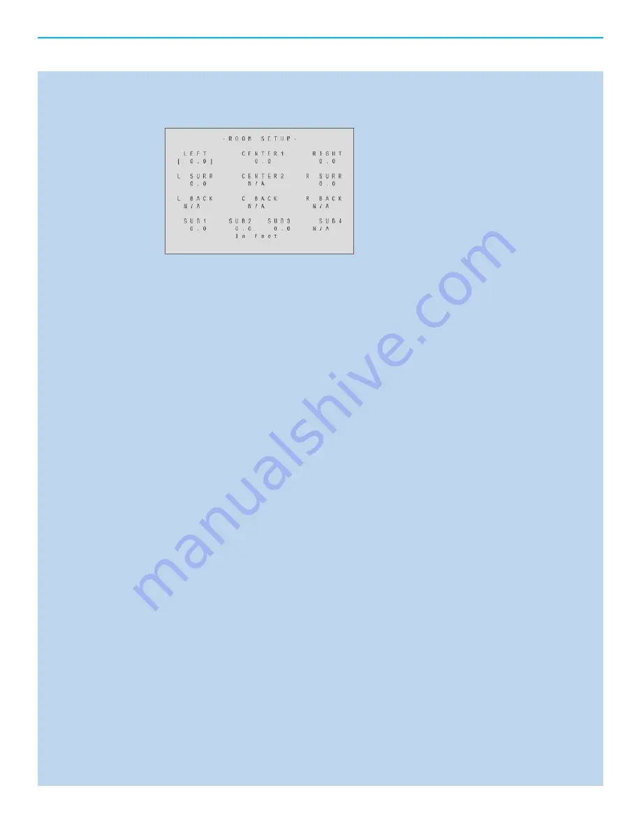
Speaker Distance –

 Defi nes the distance to each speaker in the surround sound system from the 

listening position. Each Speaker can be adjusted from 0 feet to 30 feet in .5 foot increments for 
proper arrival of sound information to the listening position. The default values are set to 0.0 feet, 
speakers labeled N/A have not been enabled in the listening room setup and are inactive.

LEFT, RIGHT

 - Speaker channels positioned front Left and front Right respective to the 

listening position. Left and right are required for a 5.1 or 7.1 surround system.

CENTER1, CENTER2

 - Speaker channels positioned front Center respective to the listening 

position. For large rooms 2 center channels can be utilized. Typically a center channel is 
positioned above or below the video screen. For really large rooms with large screens, 
centers can also be placed side by side to increase the center image width and increase 
output. They also are placed above and below for additional output in large rooms. The 
center channel is required for a 5.1 or 7.1 surround system.

L SURR, R SURR

 - Speaker channels positioned to the Left and Right midway into the  

room respective to the listening position. They can also be placed further back or behind 
the listening position in 5.1 systems. Surround channels are required for a 5.1 or 7.1 
surround system.

L BACK, R BACK

 - Speaker channels positioned to the Left and Right behind the listening 

position respectively. Rear Surround channels are required for a 7.1 surround system.

SUB1, SUB2, SUB3, SUB4

 - Speaker channel (s) specifi cally utilized for LFE (Low  

Frequency Effects) information. The Evolution 707 can accommodate up to 4 separate 
subwoofers. This can be very effective in the creation of life like surround presentation. 
subwoofers are the .1 in a 5.1 or 7.1 surround system.  The LFE channel is specifi cally 
developed to carry Low frequency energy and effects in this frequency range. In a 
traditional surround system the .1 or LFE channel will not have a lot of musical information. 
The 707 can route low frequency musical information to the subwoofers as well as the LFE 
information. With multiple subwoofers the signal can have a dedicated LFE channel and a 
dedicated low frequency speaker.  

3.

A.

B.

C.

D.

E.

Summary of Contents for Evolution 707

Page 1: ...EVOLUTION 707 OWNER S REFERENCE ...

Page 2: ...its or cold solder joints CONTACT INFORMATION Krell Industries LLC 45 Connair Road Orange CT 06477 3650 USA TEL 203 799 9954 FAX 203 891 2028 E MAIL krell krellonline com WEBSITE http www krellonline com Krell is a registered trademark of Krell Industries LLC and is restricted for use by Krell Industries LLC its subsidiaries and authorized agents Krell Current Mode is a trademark of Krell Industri...

Page 3: ...isplay 16 Connection and Operation of the OSD 16 AC Power cord connection 16 Video output Connection 16 5 Power Button 16 6 Menu Button 16 Main Menu Navigation and Setup 17 CONFIGURE VIDEO OUTPUT 17 Overview 17 Analog Video Scaler 17 Setting maximum Video output resolution 17 Setting Zone 2 video output resolution 17 LISTENING ROOM SETUP 18 Overview 18 Configure Speakers 18 Quantity 18 Full Range ...

Page 4: ...22 CONFIGURE DEVICES 23 Overview 23 Defining inputs and outputs for audio and video sources 23 Video input and output connections 23 Digital Video Options 23 HDMI Analog Video Options 23 Component Video S Video Composite Video Audio Input and Output connections 24 Digital Audio Options 24 HDMI Optical S PDIF Coaxial S PDIF 2 Analog Audio Options 24 CAST Balanced Single Ended Multi Channel H I 3 A ...

Page 5: ...o 27 Assigning Audio Inputs 27 Analog 28 Digital 28 Lip Sync 28 EQ Memory 28 Setting the Analog audio Input 28 Analog 28 Digital 28 Choosing an Analog Decode Preference 28 Auto Migration 29 Choosing a Digital Decode Preference 29 Assign Lip Sync Delay 31 Assign EQ Memory 31 Configure Trigger 32 Overview 32 Configure Trigger 32 Delay 32 2 3 A 1 2 4 A 1 2 3 4 B 1 2 C D E F G 5 A B C ...

Page 6: ...4 Maximum Volume Limit 34 Zone 2 Level 34 OPERATION 35 Overview 35 OSD Operation 35 OSD On Time 35 Line Number 35 Menu Back ground 35 Transparent Solid LCD Contrast 35 Audio Operation 35 Mute Mode 35 Dolby Hold Mode 35 DTS Mode Hold 35 EX Auto Switching 35 Dynamic Range 35 5 1 Input Setup 36 Program Remote 36 System Information 36 1 2 3 A B 4 5 6 7 8 1 2 A B C 1 2 D 3 A B C D E 4 5 6 ...

Page 7: ...quency 40 3 Shape 40 4 Level 40 Apply 40 Basic Operation of the Evolution 707 41 Power On Off and Stand By 41 Volume Control 41 Quick level adjustment buttons 41 Center Surr Back Sub Bal EQ assignment Zone 2 Output 41 Tape VCR inputs and outputs 42 Button Mode Presets 42 Save and Recall 42 Factory Reset 42 7 A B C D 1 a b c d e f E 1 2 3 A B C D E F 4 5 6 7 8 ...

Page 8: ...3 RS 232 Control 44 RS 232 Code Set Preparing for RS 232 Connectiviity 44 Settings 44 Notes 44 Code Diagram 44 RS 232 Feedback 48 RC 5 Control 58 RC 5 Code Set 58 Preparing for RC 5 Connectivity 58 Settings 58 Notes 58 Code Diagram 59 Questions and Answers 61 Warranty 62 Service 63 1 2 1 2 3 4 1 2 3 4 ...

Page 9: ...rable to a user s preferences Features and Functions The Evolution 707 includes 8 4 channels of audio output In addition to the standard 7 1 channels available in conventional surround sound processors the Evolution 707 includes a second center channel for positioning above and below screen applications and three additional subwoofer outputs Subwoofer options include multiple left right front back...

Page 10: ... S video via DIN connectors 3 Composite Video via RCA connectors OUTPUTS ANALOG AUDIO 12 CAST via CAST Connectors R L C1 C2 SR SL SBR SBL S1 S2 S3 S4 12 Balanced via XLR Connectors R L C1 C2 SR SL SBR SBL S1 S2 S3 S4 12 Single ended via RCA Connectors R L C1 C2 SR SL SBR SBL S1 S2 S3 S4 1 Tape out via RCA connectors 1 VCR audio out via RCA connectors 1 Zone 2 out via RCA connectors DIGITAL AUDIO 1...

Page 11: ...D Dolby Digital Plus Dolby Digital Dolby Digital EX Dolby Pro Logic IIx DTS HD Master Audio DTS HD High Resolution Audio DTS Digital Surround ES Neo 6 96 24 PCM 5 1 PCM 7 1 PREAMP Direct Analog Only PREAMP 5 1 Direct Analog Only SURROUND ENHANCEMENT MODES General Admission Front Row On Stage Enhanced Stereo Orchestra Mezzanine Full Range Sub Monophonic Party RS 232 DB9 Pin Out 1 Data Carrier Detec...

Page 12: ...9 Vrms Audio Input Impedance Balanced 475 KΩ Single Ended 47 KΩ Audio Output Impedance Balanced 150 Ω Single Ended 150 Ω Power Consumption Stand by 178W Operation 196W DIMENSIONS Inches L 21 22 x W 17 25 x H 8 75 Centimeters L 53 90 x W 43 82 x H 22 23 WEIGHT 52lbs Unit only 23 59kg Unit only 64lbs Shipping Weight 29 03kg Shipping weight All operational features functions and specifications are su...

Page 13: ... space with other electronics that generate heat like power amplifiers Please consult an authorized KRELL dealer or KRELL industries to insure proper installation guidelines Accessories included 1 AC Power cord 1 Handheld Remote control 1 Trigger cable 1 Owner s reference 1 Quick start guide 1 Warranty registration card 2 AAA Batteries 1 T 10 torx wrench AC Power Guidelines The Evolution 707 is de...

Page 14: ...ideo output 29 Coaxial digital output 6 Tape output 18 Zone 2 Composite video output 30 EIAJ optical digital output 7 Zone 2 analog audio outputs 19 S video output 31 Auxiliary digital interface 8 VCR audio input 20 Zone 2 S video output 32 Coaxial digital inputs 9 VCR audio output 21 12v Trigger input 33 EIAJ optical digital inputs 10 Component video inputs 22 RS 232 control port 34 Balanced audi...

Page 15: ...button 5 Quick Preamp Mode Button 19 Mute audio select 6 Quick Stereo Mode Button 20 Setup memory recall 7 Quick Mode 1 Button 21 Save system setup 8 Quick Mode 2 Button 22 Zone 2 PWR button 9 Quick Dolby Pro Logic Button 23 Microphone Input 10 Quick Surr Back channel adjust 24 IR receive window 11 Quick Sub channel adjust 25 Power Standby button 12 Balance adjust 26 Device input select 13 Navigat...

Page 16: ...s Use composite video if you are uncertain as to the video display s capabilities NOTE When using the HDMI output for OSD do not connect an HDMI input at this time It can make initial setup more difficult as the Evolution 707 will be communicating with the source before the setup of inputs and outputs has occurred Press the Power button on the front panel Within a few seconds the video display wil...

Page 17: ...80 60Hz 720p 1280 x 720 60Hz 1080p 1920 x 1080 30Hz 480p 720 x 480 60Hz 1080i 1920 x 1080 50Hz Outside the USA 1080p 1920 x 1080 50Hz Outside the USA 576i 720 x 576 50Hz Outside the USA 1080i 1920 x 1080 60Hz 1080p 1920 x 1080 60Hz 576p 720 x 576 50Hz Outside the USA 1080p 1920 x 1080 24Hz 720p 1280 x 720 50Hz Outside the USA 1080p 1920 x 1080 25Hz Outside the USA Setting Zone 2 video output resol...

Page 18: ...FE channels for each group of speakers in the surround system The quantity and frequency options are available for each group of speakers listed below Quantity Sets the number of channels in the system Full Range This setting allows the passing of full spectrum audio frequencies including LFE information LIM limited Hz Sets the low pass filter frequency Low frequency information below this setting...

Page 19: ...a higher output level is required Surround Speaker channels positioned to the Left and Right midway into the room respective to the listening position Quantity NO 1 and 2 Crossover Full LIM Hz Back Speaker channels positioned to the Left and Right behind the listening position respectively Quantity NO 1 and 2 Crossover Full LIM Hz 5 1 Surround This setting allows the steering of surround informati...

Page 20: ... low frequency from speakers in the BACK set to limited as well as the LFE effects are sent to the subwoofer s LEFT LFE LFE and Subwoofer functions are enabled all low frequency from speakers on the LEFT side set to limited as well as the LFE effects are enabled RIGHT LFE LFE and Subwoofer functions are enabled All low frequency from speakers on the RIGHT side set to limited as well as the LFE eff...

Page 21: ...er channel is required for a 5 1 or 7 1 surround system L SURR R SURR Speaker channels positioned to the Left and Right midway into the room respective to the listening position They can also be placed further back or behind the listening position in 5 1 systems Surround channels are required for a 5 1 or 7 1 surround system L BACK R BACK Speaker channels positioned to the Left and Right behind th...

Page 22: ...etup program will stay on each speaker channel for approximately 3 seconds and then move to the next speaker channel Once finished to exit from the auto noise sequence menu press the previous button or the menu button Manual Noise Sequence The manual noise sequence works similarly to the Auto Noise sequence the major difference being that the automatic portion has been removed In manual mode navig...

Page 23: ...dicated signal paths for Red Blue and Green This video standard also supports uncompressed video but does not carry audio data and would require the use of an audio interface to be used in conjunction There are 3 Component video inputs 1 output and 1 zone 2 output The Evolution 707 uses RCA connections for component video S video Separate Video A standard definition connection featuring a data pat...

Page 24: ...gital DTS and PCM standards S PDIF can decode A Maximum of 2 channel 24 96 24bit 96Khz data or 8 channels of 24 48 24bit 48Khz There is no difference in the signal transmission between coaxial and optical data is carried over a 75ohm coaxial cable instead of being optically transferred There are 4 coaxial inputs and 1 output The Evolution 707 uses RCA connections for S PDIF coaxial digital audio 2...

Page 25: ...707 uses XLR connections for balanced audio Single Ended The original standard for transferring audio signals using a single conductor and ground termination Single ended connections do not have the same performance benefits as Balanced or CAST terminations There are 5 single ended inputs 1 Tape input 1 VCR input 12 outputs 1 Tape output 1 VCR output and 1 Zone 2 output The Evolution 707 uses RCA ...

Page 26: ...quired a second analog video input connection is necessary Setting the Main Video Input Using the arrow keys navigate to the text below the device label Press the enter button to make the text flash while flashing and using the up and down arrows select the device input to be changed by pressing the enter button Navigate to the text below the Main Video Input label and press Enter this will make t...

Page 27: ...and the sound leaving their mouth Normally this synchronization will be correct but in systems where multiple video connections are made or extreme distances are required a delay can be present The lip Sync setting can increase the audio delay in milliseconds to match video presentation EQ Memory Sets the room equalization mode configured in the operation menu There are up to 4 different EQ settin...

Page 28: ... audio transport known as S PDIF typically used for earlier sources that have audio over HDMI in an S PDIF format For this type of source use the HDMI S option These source units may not transfer audio on the advanced HDMI audio transport NOTE HDMI audio inputs are defined by the Video selection S PDIF Optical TOSLINK OPT 1 OPT 2 OPT 3 OPT 4 S PDIF Coaxial COAX 1 COAX 2 COAX 3 COAX 4 Disabled No a...

Page 29: ...igital signal it will default to that format for sound if it does not sense the digital signal it will switch to the analog input allowing analog signal to pass The options for Auto Migration are OFF and ON NOTE If both sets of inputs are not used simultaneously for any given button preset it is recommended to keep Auto Migration OFF Choose a Digital Decode Preference The Digital decode preference...

Page 30: ...Hz DTS NEO 6 Cinema 44 1 48 96 kHz DTS NEO 6 Music 44 1 48 96 kHz Party 44 1 48 96 192 kHz General Admission 44 1 48 96 192 kHz Front Row 44 1 48 96 192 kHz On Stage 44 1 48 96 192 kHz Enhanced Stereo 44 1 48 96 192 kHz Orchestra 44 1 48 96 192 kHz Mezzanine 44 1 48 96 192 kHz Full Range Sub 44 1 48 96 192 kHz Monophonic 44 1 48 96 192 kHz Stereo 44 1 48 96 192 kHz 1 2 1 2 3 1 2 3 4 5 6 7 8 9 10 1...

Page 31: ... the right of the Delay label press enter and change the Lip Sync delay The delay can be adjusted from 0 200ms Assign EQ Memory To adjust the EQ Memory options Use the arrow keys to navigate to the text to the right of the device label Press the enter button to make the text flash while flashing and using the up and down arrows select the device input to be changed by pressing the enter button Nav...

Page 32: ... All triggers If the all triggers option is selected then the Mode and delay will be configured for all 4 trigger outputs for that selected button preset If Selective is used then each trigger can be configured individually for that button preset The selective options are Trigger 1 Trigger 2 Trigger 3 and Trigger 4 NOTE Trigger 1 is enabled for all button presets by default Mode sets the behavior ...

Page 33: ... function measures the signal level and prevents the input signal from overloading clipping the analog to digital converters The Anti clip option is ON or OFF Input Gain Increase or decreases the analog input signal for optimum performance The input gain range is from 6dB to 6dB in 1dB increments To maximize your system s signal to noise ratio without clipping increase the input gain value applied...

Page 34: ...to 7 highest effectively mutes the center channel in 1 dB increments Dimension Adjust the fade balance between the front or rear loudspeakers to customize the balance from all loudspeakers The adjustment range is from 0 Maximum surround to 6 Maximum front The default setting is 4 neutral and adjustable in 1 dB increments Maximum Volume Limit Adjusts the maximum system volume control limit The maxi...

Page 35: ...front panel display Adjust the value up or down until the display text is clearly visible from the main viewing angle The LCD contrast can be adjusted from 1 to 32 Audio Operation Adjusts advanced Evolution 707 audio related functions Mute Mode Adjusts the level of attenuation used when the Mute button is depressed The options are Full for complete silence when pressed and 20dB that will drop the ...

Page 36: ...on that is not on the Evolution 707 s remote control Follow the instructions below to begin and end the program remote function To begin turn the volume control to select a command The command appears on the front panel display window Place the programmable remote in program mode see the learning remote user manual Place the infrared sensor of the programmable remote so that it faces the infrared ...

Page 37: ...ascaded and labeled I II or III Memory There are 4 memory locations for advanced EQ filters The options for Memory are 1 2 3 4 and Off Channel An EQ filter can be saved and set for any individual channel The channel options are All All of the channels are filtered in the same manner as specified in the Room EQ Setup Menu L R C LS RS LB RB or S An Individual channel filter for a specific channel NO...

Page 38: ...ow the 3 dB point changes frequency The FREQ parameter is the only parameter you can change on the HPF Notch Notch Filter Below is a graph of the Notch Filter The graph also shows what happens when you change the Shape parameter of the Notch filter Notice how the width of the notch changes The Frequency parameter of the notch filter moves the notch across the frequency band b c ...

Page 39: ...s above the crossover point specified by the FREQ parameter Pking Peaking Filter Below are two graphs of the peaking filter The peaking filter is similar to the notch but the peaking filter has the ability to vary the depth of the notch using the LEVEL parameter The depth can be changed to the point that it offers boost instead of cut The first graph shows what happens when you change the Shape pa...

Page 40: ... 4 to 9 0 4 Level The Peaking High Shelf and Low Shelf filters require a level adjustment The input level to the filter is reduced allowing the filter to pass full scale input at the filter s peak level without clipping the signal The level difference is made up in the volume control so the peak of the filter is really above below the un filtered level and the un filtered levels are the same as th...

Page 41: ...l up or down 10dB to 10dB in 1dB increments Additionally if the Center button is pressed twice it will enable a Phantom Center mode Phantom center is designed to route center channel information to the Left and Right speakers creating a center channel when there is in affect no center channel speaker Surr Adjusts the left and right surround channel output levels 10dB to 10dB in 1dB increments Back...

Page 42: ...to a default layout Once a layout has been saved it can be recalled at anytime restoring back to the last saved working presets To Save a layout Press and Hold the Save button on the Front panel The front panel display will show Saving Setup and return to its last activity To Recall a layout Press and Hold the Recall button on the Front panel The front panel display will show Recall Setup the Init...

Page 43: ...the Factory for information regarding firmware updates Future Upgrades A B C D modes options Not available at this time There are 4 buttons on the Remote control and also the front panel under the front panel display They will be enabled as quick access modes in the near future These updates will be available via a firmware update Please consult Krell industries for details Mic Input Not available...

Page 44: ...s active then commands can be sent Feedback can be received when the unit is in stand by mode The Evolution 707 and All Krell components require a straight non nulling RS 232 cable Settings The RS 232 protocol settings for status and control are as follows 9600 Baud 8 Data Bits 1 Stop Bit No Parity DB 9 Pin out Data Carrier Detect Received Data Transmitted Data Data Terminal Ready Signal Ground Da...

Page 45: ... 020 sets 10 to 10 dB XXXSVLZ Subwoofer 2 trim 000 020 sets 10 to 10 dB XXXS2LZ Subwoofer 3 trim 000 020 sets 10 to 10 dB XXXS3LZ Subwoofer 4 trim 000 020 sets 10 to 10 dB XXXS4LZ Current Zone Balance Select then use UPZ and DWNZ IBALZ Balance 000 026 sets right off left 6 through right 6 left off 1 2 dB steps XXBALZ Remote Zone Balance then use UPZ and DWNZ BRLZ Mute Current Zone MUTZ Mute Main Z...

Page 46: ...1 4 xxxEQMZ Trigger Commands Video Direct Select Commands works on selected zone Select Main Zone for Video Direct Select DIMZ Select Zone 2 for Video Direct Select DI2Z HDMI video 1 HM1Z HDMI video 2 HM2Z HDMI video 3 HM3Z HDMI video 4 HM4Z Component video 1 CM1Z Component video 2 CM2Z Component video 3 CM3Z Composite video 1 CS1Z Composite video 2 CS2Z Composite video 3 CS3Z Composite video 4 CS...

Page 47: ...y Digital 2 0 Stereo Mode Pass Mode 002 Dolby Digital 2 0 Pro Logic IIx Movie Mode 003 Dolby Digital 2 0 Pro Logic IIx Music Mode 007 DTS 5 1 Music 008 DTS 5 1 Movie 009 DTS 5 1 Matrix 010 DTS 6 1 Discrete 011 Stereo Mode Pass Mode 012 Pro Logic IIx Movie Mode 013 Pro Logic IIx Music Mode 017 DTS Neo 6 Cinema 6 Mode 018 DTS Neo 6 Music Mode 019 Party Mode 020 General Admission Mode 021 Front Row M...

Page 48: ...d ASTEZ Once this command is sent the Evolution 707 will transmit a status block whenever the status changes Auto Status is disabled by sending the RS 232 command ASTDZ Auto Status remains enabled until AC power is removed or turned off All numeric values described in the following are decimal values unless otherwise noted The description of the eighteen 8 bit words are as follows WORD 1 Start of ...

Page 49: ...rigger 2 on 1 Trigger 2 is on Bit 1 Trigger 1 on 1 Trigger 1 is on Bit 0 DSP Running 1 DSPs are not reset WORD 4 Current Device Bit 7 6 5 4 3 2 1 0 Z2 CD3 Z2 CD2 Z2 CD1 Z2 CD0 MN CD3 MN CD2 MN CD1 MN CD0 Bits 7 4 Zone 2 Current Device Bits 3 0 Main Zone Current Device Devices 0 DVD 1 DVDR 2 SAT 3 VCR 4 TV 5 CD 6 TUNER 7 DVR 8 GAME 9 TAPE WORD 5 Main Volume Bit 7 6 5 4 3 2 1 0 VOL 7 VOL 6 VOL 5 VOL...

Page 50: ...Video 3 Composite Video 4 Composite Video 5 Composite Video 6 HDMI Video 1 HDMI Video 2 HDMI Video 3 HDMI Video 4 WORD 8 Main Zone Audio Input Bit 7 6 5 4 3 2 1 0 MN AUD IN 7 MN AUD IN 6 MN AUD IN 5 MN AUD IN 4 MN AUD IN 3 MN AUD IN 2 MN AUD IN 1 MN AUD IN 0 Bit 7 0 Main Zone Audio Input Audio Inputs 1 Digital COAX 1 2 Digital COAX 2 3 Digital COAX 3 4 Digital COAX 4 5 Digital Optical 1 6 Digital ...

Page 51: ...B1 12 Analog S1 13 Analog S2 15 Analog S3 15 Analog S4 16 Analog S5 17 Analog Tape 23 Analog VCR 24 Analog Cast 1 25 Analog Cast 2 WORD 10 Speakers Current Audio Decode Mode Bit 7 6 5 4 3 2 1 0 Back Enabled Sub Enabled Surround Enabled Center Enabled Input Stream 3 Input Stream 2 Input Stream 1 Input Stream 0 Bit 7 Back Enabled 1 Back Speaker s is are enabled Bit 6 Sub Enabled 1 Subwoofer is enabl...

Page 52: ... XY AAC 1 1 Multi Channel Preamp HDMI IIS HDMI PCM2 WORD 11 Current Audio Decode Modes Bit 7 6 5 4 3 2 1 0 CAD 7 CAD 6 CAD 5 CAD 4 CAD 3 CAD 2 CAD 1 CAD 0 Bit 7 0 Current Audio Decode Modes Hex Decimal IF Stream ID 6 6 PCM Digital Stereo Mode Pass Mode 1 1 Pro Logic IIx Movie Mode 2 2 Pro Logic IIx Music Mode 3 3 Multi Channel Input Mode 7 7 DTS Neo 6 Cinema 6 Mode 9 9 2496 decode mode 0A 10 DTS N...

Page 53: ...0 DTS Neo 6 Music Mode 0B 11 DTS Neo 6 Cinema 6 THX Mode 0C 12 Party Mode 0E 14 General Admission Mode 0F 15 Front Row Mode 10 16 On Stage Mode 11 17 Enhanced Stereo Mode 12 18 Orchestra Mode 13 19 Mezzanine Mode 14 20 Full Range Sub Mode 15 21 Monophonic Mode 16 22 Analog only preamp mode 17 23 IF Stream is Dolby Digital Stream ID 2 2 Dolby Digital Stereo Mode Pass Mode 18 24 Pro Logic IIx Movie ...

Page 54: ...am is AAC 20 Stream ID E 14 AAC 2 0 AAC 2 0 4b 75 IF Stream is AAC 51 Stream ID E 14 AAC 5 1 AAC 5 1 4f 79 IF Stream is AAC 11 Stream ID 11 17 AAC 1 1 AAC 1 1 4a 74 AAC 1L1 55 85 AAC 1R1 56 86 IF Stream is AAC XY Stream ID 10 16 AAC XY AAC 1 0 58 88 AAC 3 0 4c 76 AAC 3 1 4d 77 AAC 3 2 4e 78 AAC 7 1 50 80 IF Stream is HDMI Stream ID 13 19 HDMI Auto HDMI PCM 2 Channel D8 216 HDMI PCM 5 1 Channel DD ...

Page 55: ... 14 20 Full Range Sub Mode 15 21 Monophonic Mode 16 22 Analog only preamp mode 17 23 WORD 12 Main Zone Balance Compression Mode Bit 7 6 5 4 3 2 1 0 Reserved Cmode 1 Cmode 0 BAL 4 BAL 3 BAL 2 BAL 1 BAL 0 Bits 4 0 Balance Setting 0 26 Bits 5 6 Compression Mode Balance Settings 0 Right Off 9 Left 2 0 18 Right 2 5 Left 6 10 Left 1 5 19 Right 3 0 Left 5 5 11 Left 1 0 20 Right 3 5 Left 5 0 12 Left 0 5 2...

Page 56: ... 5 19 Right 3 0 10 Left 5 5 11 Left 1 0 20 Right 3 5 11 Left 5 0 12 Left 0 5 21 Right 4 0 12 Left 4 5 13 Centered 22 Right 4 5 13 Left 4 0 14 Right 0 5 23 Right 5 0 14 Left 3 5 15 Right 1 0 24 Right 5 5 15 Left 3 0 16 Right 1 5 25 Right 6 0 16 Left 2 5 17 Right 2 0 26 Left Off WORD 14 Center Trim Bit 7 6 5 4 3 2 1 0 Reserved Reserved Reserved CT 4 CT 3 CT 2 CT 1 CT 0 Bits 4 0 Center Trim Trim Sett...

Page 57: ...T 4 BT 3 BT 2 BT 1 BT 0 Bits 4 0 Back Trim Trim Settings 0 10 dB 6 4 dB 12 2 dB 18 8 dB 1 9 dB 7 3 dB 13 3 dB 19 9 dB 2 8 dB 8 2 dB 14 4 dB 20 10 dB 3 7 dB 9 1 dB 15 5 dB 4 6 dB 10 0 dB 16 6 dB 5 5 dB 11 1 dB 17 7 dB WORD 17 Sub Trim Bit 7 6 5 4 3 2 1 0 Reserved Reserved Reserved ST 4 ST 3 ST 2 ST 1 ST 0 Bits 4 0 Sub Trim Trim Settings 0 10 dB 6 4 dB 12 2 dB 18 8 dB 1 9 dB 7 3 dB 13 3 dB 19 9 dB 2...

Page 58: ...07 is designed to receive un modulated data only The input does supply power 5v to be used with several IR receiving devices NOTE When the RC 5 IR receiver port is in use the front panel IR receiver is disabled Settings Settings will vary for different remote devices the table below describes code sets commenly used for popular remote control systems RC 5 Cable Pin out A stereo tip ring sleeve 1 8...

Page 59: ...000 0000 0001 001C 0021 COAX2 1C 22 28 34 3722 5000 0000 0000 0001 001C 0022 OPT1 1C 23 28 35 3723 5000 0000 0000 0001 001C 0023 OPT2 1C 24 28 36 3724 5000 0000 0000 0001 001C 0024 OPT3 1C 25 28 37 3725 5000 0000 0000 0001 001C 0025 OPT4 1C 26 28 38 3726 5000 0000 0000 0001 001C 0026 Tape On 1C 27 28 39 3727 5000 0000 0000 0001 001C 0027 Tape Off 1C 28 28 40 3728 5000 0000 0000 0001 001C 0028 S Vi...

Page 60: ... 365E 5000 0000 0000 0001 0019 001E Z2 PWR Off 19 1F 25 31 365F 5000 0000 0000 0001 0019 001F Pre Amp 19 23 25 35 3663 5000 0000 0000 0001 0019 0023 SELECT Z2 Direct 19 26 25 38 3666 5000 0000 0000 0001 0019 0026 SELECT MAIN Direct 19 27 25 39 3667 5000 0000 0000 0001 0019 0027 Max Dynr 19 28 25 40 3668 5000 0000 0000 0001 0019 0028 Night Dynr 19 29 25 41 3669 5000 0000 0000 0001 0019 0029 Norm Dy...

Page 61: ...from the processor and then amplifiers to speakers If all seems to be in working order check to see if the Evolution 707 is in Phantom Center mode this can be enabled by pressing the center quick select button twice which will disable the physical center channel and redirect center information to the left and right speakers Q When I play a standard DVD on my Blu ray machine the video works fine bu...

Page 62: ...n freight within the United States U S A is included in the warranty If you have purchased your Krell product outside the U S A and wish to have it serviced at the factory all freight and associated charges to the fac tory are your responsibility Krell will pay return freight to the U S A based freight forwarder of your choice Freight and other charges to ship the unit from the freight forwarder t...

Page 63: ...ered if arrangements with the Service Department have been made in advance Proof of purchase will be required for warranty validation at the time of hand delivery NOTE Use the original packaging to ensure the safe transit of the product to the factory dealer or distributor Krell may at its discretion return a product in new packaging and bill the owner for such packaging if the product received by...

Reviews: