background image

KRAMER:  SIMPLE CREATIVE TECHNOLOGY


Using Your WP-500 


5.1.1 

Connecting the Microphone 

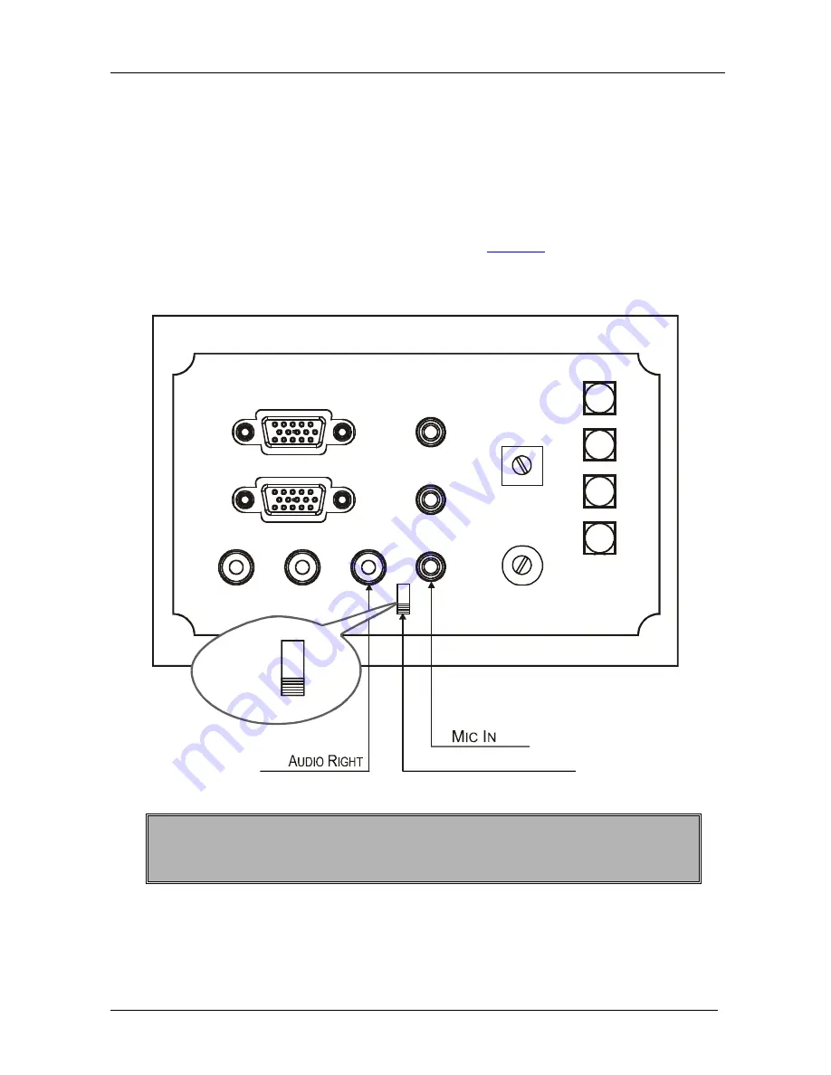
You can connect either a dynamic or a condenser microphone to the MIC IN 
3.5mm mini jack.  

Before connecting the microphone, set the microphone mode switch to dynamic 
or condenser (by default, this switch is set to dynamic). 

The Dyn/Cond mode switch is located behind the front panel on the lower left 
side of the MIC IN 3.5mm jack, as illustrated in 

Figure 5

It is recommended to set the mic mode switch before mounting the 

WP-500

 front 

panel. 

Dyn/Cond Mode Switch

Cond

Dyn

CV


Figure 5: Setting the Microphone Mode Switch 

When disconnecting the microphone or switching it OFF, turn the 

microphone volume adjustment knob to the left (MIC mute). 

When using the microphone, pay attention to the placement of the speakers. By 
placing the speakers properly, the chance of getting audio feedback is minimized. 


Summary of Contents for WP-500

Page 1: ...Kramer Electronics Ltd USER MANUAL Model WP 500 Wall Plate Solution for Simple Room Control and Signal Switching...

Page 2: ...WP 500 9 6 Technical Specifications 10 Figures Figure 1 WP 500 Front Panel 3 Figure 2 WP 500 Rear Panel 4 Figure 3 Connecting the WP 500 Front Panel 6 Figure 4 Connecting the WP 500 Rear Panel 7 Figu...

Page 3: ...ate Kramer K Config Guide available online for details of how to install and configure the Room Controller 3 We recommend that you review the contents of this user manual 3 Overview The WP 500 is an a...

Page 4: ...and support EDID communication with the connected PC sources the default EDID is uploaded upon delivery a specific EDID can be uploaded by the user via the Kramer FC 200 XGA EDID Copier2 Has a USB po...

Page 5: ...Connect to the unbalanced stereo audio signal of the PC2 source 6 PC 1 Inputs 15 Pin HD Connector Connect to the PC 1 source AUDIO 1 3 5mm mini jack Connect to the unbalanced stereo audio signal of th...

Page 6: ...remote control and management from the Kramer Site CTRL software and for remote configuration file and firmware updates upload 7 Grounding Screw Connect to grounding wire 8 RS 232 Port Connect to the...

Page 7: ...500 To connect the WP 500 as illustrated in the example in Figure 3 front panel and Figure 4 rear panel do the following 1 On the front panel see Figure 3 connect A computer graphics source and the a...

Page 8: ...VIDEO OUT GND to the video input on the projector AUDIO OUT 1 and AUDIO OUT 2 outputs to the audio input of the video and PC inputs on the projector1 RS 232 port to the PC control port of the project...

Page 9: ...Using Your WP 500 7 Figure 4 Connecting the WP 500 Rear Panel...

Page 10: ...ted behind the front panel on the lower left side of the MIC IN 3 5mm jack as illustrated in Figure 5 It is recommended to set the mic mode switch before mounting the WP 500 front panel Dyn Cond Mode...

Page 11: ...e PC input PC 1 Select the PC 1 input of the projector Stop the DVD player Power down the DVD player PC 2 Select the PC 2 input of the projector Stop the video player VIDEO CV Select the VIDEO CV inpu...

Page 12: ...LT EDID INFORMATION Standard timings supported 640x480px60Hz IBM VGA 640x480px67Hz Apple Mac II 640x480px72Hz VESA 640x480px75Hz VESA 800x600px56Hz VESA 800x 600px60Hz VESA 800x600px72Hz VESA 800x600p...

Page 13: ...heractsofnature ii Product modification orfailureto followinstructions supplied with theproduct iii Repairorattemptedrepairby anyonenot authorized byKramer iv Anyshipment oftheproduct claims must bepr...

Page 14: ...or the latest information on our products and a list of Kramer distributors visit our Web site www kramerelectronics com where updates to this user manual may be found We welcome your questions commen...

Reviews: