


KRAMER: SIMPLE CREATIVE TECHNOLOGY
Defining the WP-500
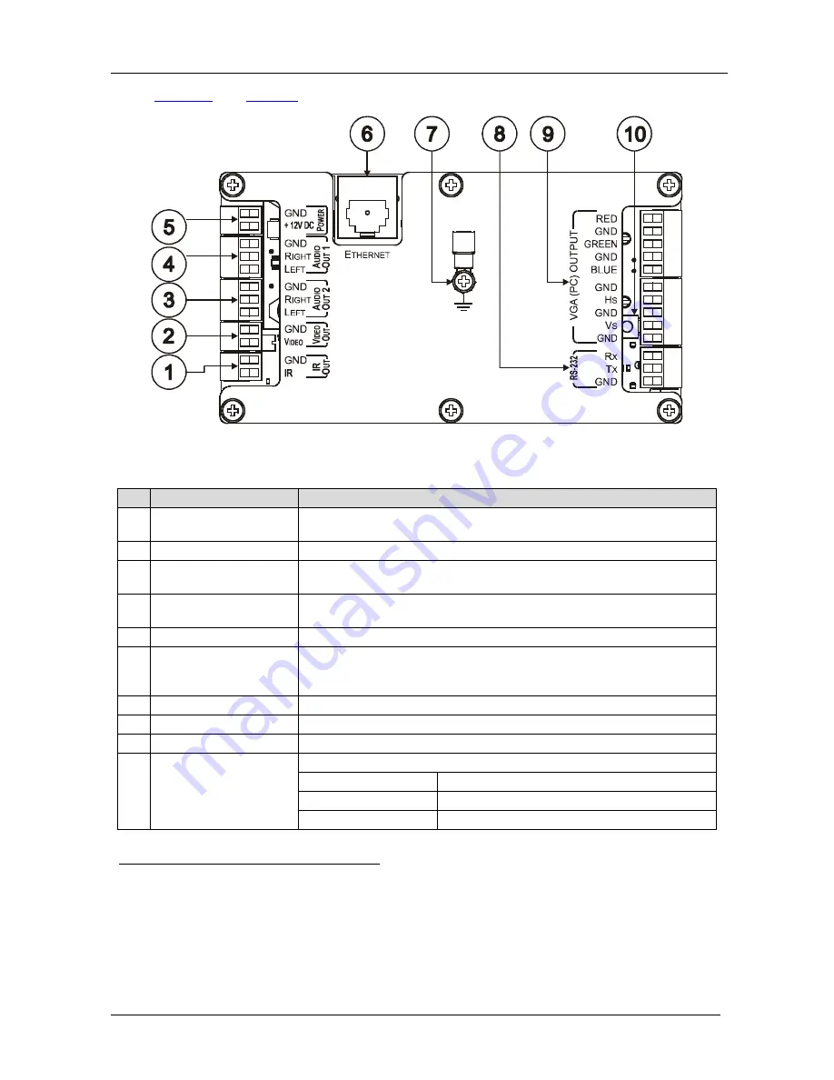
4
Figure 2
and
Table 2
define the
WP-500
rear panel:
Figure 2: WP-500 Rear Panel
Table 2: WP-500 Rear Panel Features
#
Feature
Function
1
IR OUT
Controls the display device via an IR emitter (for example, in cases
where RS-232 control is not available)
2
VIDEO OUT
Connect to the video IN of the display device
3
AUDIO OUT 2
1
Connect to the audio input associated with the Video Input channel of
the display device
4
AUDIO OUT 1
1
Connect to the audio input associated with the PC graphics Input
channel of the display device
5
+ 12V DC
Connect to power the unit
6
ETHERNET Port
Connect to the local computer network for accessing the stored Web
pages, for remote control and management from the Kramer Site-CTRL
software and for remote configuration file and firmware updates upload
7
Grounding Screw
Connect to grounding wire
8
RS-232 Port
Connect to the RS-232 connector on the display device
9
VGA (PC) OUTPUT
Connect to the PC graphics IN of the display device
10
Factory Reset Button
2
Push
3
to erase the configuration and reset to the factory default definitions
4
:
IP Address:
192.168.1.39
Mask:
255.255.0.0
Gateway:
0.0.0.0
1 Both output ports are identical
2 This operation should be carried out by authorized Kramer technical personnel or by an external system integrator, and
requires removal of the device from the wall by unscrewing the four wall mount screws
3 Using a small screwdriver
4 Disconnect the power and then connect it while pressing the Factory Reset button. The unit will power up and load its
memory with the factory default definitions


