background image


RB-6 - Defining the RB-6 6 Channel Power Controller 


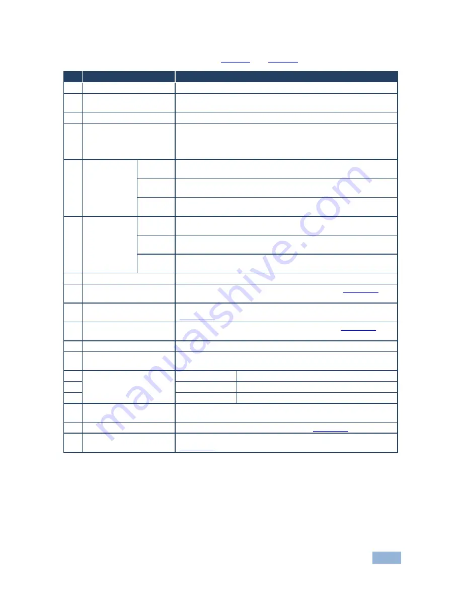
The following table refers to both 

Figure 1

 and 

Figure 2


Feature 

Function 

IR

 Receiver 

Infrared remote control sensor 

IR

 LED 

Lights yellow when receiving commands from the IR remote control 
transmitter 

POWER 

LED 

Lights green when the device is powered on 

ACTIVE OUTPUTS


Buttons (1 to 4)


Press a button to turn on the output. The relevant button LED lights 
red. 
Press the button again to turn the output off. The button LED no 
longer lights 

ACTIVE 
OUTPUTS 5


Controls 

MAX 

Press to set the output voltage to maximum. Press and hold to set 
the current setting as the maximum voltage 

MIN 

Press to set the output voltage to minimum. Press and hold to set 
the current setting as the minimum voltage 

Rotary 
control 

Turn clockwise to increase or anti-clockwise to decrease the output 
voltage 

ACTIVE 
OUTPUTS 6


Controls 

MAX 

Press to set the output voltage to maximum. Press and hold to set 
the current setting as the maximum voltage 

MIN


Press to set the output voltage to minimum. Press and hold to set 
the current setting as the minimum voltage 

Rotary 
control 

Turn clockwise to increase or anti-clockwise to decrease the output 
voltage 

PROGRAM

 Switch


For the use of Kramer service personnel only 

RS-232

 9-pin D-sub 

Connector (F)


Connect to an RS-232 controller, such as a PC (see 

Section


 6.3

REMOTE IR

 3.5mm 

Opening


For installing the optional external IR receiver 3.5mm mini jack (see 

Section


 3.1

10 

ETHERNET

 RJ-45 

Connector


Connect to a remote PC controller over a LAN (see 

Section


 6.2

11 

OUT 1~4

 Power Sockets


Plug in devices to be controlled only on and off 

12 

OUT 5~6

 Power Sockets


Plug in devices to be controlled on/off, and a dimming function using 
the minimum/maximum rotary controls (see 5 and 6) 

13 

IN

—POWER—ON


Power Socket 

Connect to the mains power 

14 

Mains Fuse 

Fuse for protecting the RB-6 

15 

Mains Switch 

Switch for turning the device on and off 

16 

RESET

 Switch


Press and hold while turning power on to reset the device to factory 
default condition 

17 

TERM

 RS-485 Switch 

Push up to terminate the RS-485 bus (see 

Section


 6.4

18 

RS-485

 3-pin Terminal 

Block


Connect to a controller equipped with an RS-485 port (see  

Section


 6.4


im Vertrieb von            CAMBOARD Electronics

www.camboard.de

Tel. 07131 911201
Fax 07131 911203

[email protected]

Summary of Contents for RB-6

Page 1: ...RAMER ELECTRONICS LTD USER MANUAL MODEL RB 6 6 Channel Power Controller P N 2900 300024 Rev 1 im Vertrieb von CAMBOARD Electronics www camboard de Tel 07131 911201 Fax 07131 911203 ce info camboard de...

Page 2: ...im Vertrieb von CAMBOARD Electronics www camboard de Tel 07131 911201 Fax 07131 911203 ce info camboard de...

Page 3: ...Page 22 8 4 The Configurations Page 23 9 Firmware Update 25 10 Technical Specifications 26 11 Default Communication Parameters 27 12 RB 6 Communication Protocol 28 12 1 Syntax 28 12 2 Supported Comman...

Page 4: ...troduction Figure 14 Panel Page 21 Figure 15 The Scheduler Page 22 Figure 16 The Configurations Page 23 im Vertrieb von CAMBOARD Electronics www camboard de Tel 07131 911201 Fax 07131 911203 ce info c...

Page 5: ...GROUP 1 Distribution Amplifiers GROUP 2 Switchers and Routers GROUP 3 Control Systems GROUP 4 Format Standards Converters GROUP 5 Range Extenders and Repeaters GROUP 6 Specialty AV Products GROUP 7 Sc...

Page 6: ...with low quality cables Do not secure the cables in tight bundles or roll the slack into tight coils Position your Kramer RB 6 away from moisture excessive sunlight and dust This equipment is to be us...

Page 7: ...amer Electronics has made arrangements with the European Advanced Recycling Network EARN and will cover any costs of treatment recycling and recovery of waste Kramer Electronics branded equipment on a...

Page 8: ...n America with 110V AC American power sockets RB 6 is printed on the front panel of both models 3 1 Using the IR Transmitter You can use the RC IR3 IR transmitter to control the machine via the built...

Page 9: ...he RB 6 6 Channel Power Controller Figure 1 RB 6 6 Channel Power Controller Front and Rear Panels 5 RB 6 Defining the RB 6 6 Channel Power Controller Overview im Vertrieb von CAMBOARD Electronics www...

Page 10: ...ower Controller Figure 2 RB 6 US 6 Channel Power Controller Front and Rear Panels RB 6 Defining the RB 6 6 Channel Power Controller 6 im Vertrieb von CAMBOARD Electronics www camboard de Tel 07131 911...

Page 11: ...et the current setting as the minimum voltage Rotary control Turn clockwise to increase or anti clockwise to decrease the output voltage 7 PROGRAM Switch For the use of Kramer service personnel only 8...

Page 12: ...8 RB 6 Installing in a Rack 5 Installing in a Rack im Vertrieb von CAMBOARD Electronics www camboard de Tel 07131 911201 Fax 07131 911203 ce info camboard de...

Page 13: ...the RB 6 Figure 3 Connecting to the RB 6 Rear Panel To connect the RB 6 as illustrated in the example in Figure 3 1 Connect a device for example a blind system to power outlet 1 for open and to power...

Page 14: ...tp www kramerelectronics com 6 2 1 Connecting the Ethernet Port directly to a PC You can connect the Ethernet port on the RB 6 to the Ethernet port on your PC via a crossover cable with RJ 45 connecto...

Page 15: ...details as shown in Figure 5 You can use any IP address in the range 192 168 1 1 to 192 168 1 255 excluding 192 168 1 39 that is provided by your IT department Figure 5 Internet Protocol TCP IP Proper...

Page 16: ...the Ethernet port download the K Upload Ethernet configuration software The K Upload Ethernet configuration software is available from http www kramerelectronics com Extract the file to a folder and...

Page 17: ...PC to the USB port on the RB 6 you can also connect to the PC via the Ethernet or a serial connector 4 Select USB as the connection method 5 Select the com port from the USB drop down list 6 Click Co...

Page 18: ...PC A crossed cable or null modem is required as shown in method A and B respectively If a shielded cable is used connect the shield to pin 5 Method A Figure 9 Connect the RS 232 9 pin D sub port on th...

Page 19: ...3 and 5 to be connected you are free to decide whether to connect only these 3 pins or all 9 pins Figure 10 Straight Cable RS 232 Connection with a Null Modem Adapter 6 4 Connecting a PC or Controller...

Page 20: ...S 485 port of the PC to the A pin on the RS 485 port on the rear panel of the RB 6 Connect the B pin on the RS 485 port of the PC to the B pin on the RS 485 port on the rear panel of the RB 6 Connect...

Page 21: ...se the output voltage The button LED flashes for a few seconds when the maximum or minimum limit is reached then lights solid To set the output voltage to the minimum or maximum voltage on outputs 5 a...

Page 22: ...settings are the default values When a Max or Min button LED lights it indicates that there is a custom setting 7 2 Resetting the RB 6 to Factory Defaults To reset the device to factory defaults 1 Tur...

Page 23: ...to the RB 6 via the Ethernet connection see Section 6 2 The Java software is available from http www java com A description of each Web page appears if you hover with your mouse over the question mar...

Page 24: ...a and JavaScript is enabled in your browser The security warning shown in Figure 13 appears Figure 13 Security Warning 3 Click Run The RB 6 Panel page appears with the menu on the left side of the scr...

Page 25: ...ton changes to purple To turn an output off Click the required purple output Relay button The relay is turned off and the button changes to white To change the voltage on Output 5 or 6 1 Click and hol...

Page 26: ...schedule for the selected channel s the Time ON and the Time OFF Click Add to add the schedule for the selected channel s Click Read to read the current schedule stored in the machine the schedule fro...

Page 27: ...meters the device name IP address DHCP gateway and subnet mask as well as view others model serial number firmware version and MAC address Figure 16 The Configurations Page To change configuration set...

Page 28: ...s 4 Click OK 5 If the IP address was changed communication with the device is lost Close the Web page and reload the Web page with the new address im Vertrieb von CAMBOARD Electronics www camboard de...

Page 29: ...e of the RB 6 refer to the K Upload Software Guide available for download from http www kramerelectronics com Note You cannot perform a firmware upgrade using the RS 485 port im Vertrieb von CAMBOARD...

Page 30: ...of 10A Max USA 5 x 100 120V AC outputs total load of 10A Max MAXIMUM LOAD 10A total 6A per socket OPERATING TEMPERATURE 0 to 40 C 32 to 104 F STORAGE TEMPERATURE 40 to 70 C 40 to 158 F HUMIDITY 10 to...

Page 31: ...8 Stop Bits 1 Parity None Command Format Hex Example Output 1 to Input 1 0x01 0x81 0x81 0x81 Ethernet IP Address 192 168 1 39 TCP Port Number 5000 Network Mask 255 255 255 0 Default Gateway 192 168 1...

Page 32: ...tax 12 1 1 Host Message Format Start Address optional Body Delimiter Destination_id Message CR 12 1 1 1 Simple Command Command string with only one command without addressing Start Body Delimiter Comm...

Page 33: ...e separated by commas Message string Every command entered as part of a message string begins with a message starting character and ends with a message closing character Note A string can contain more...

Page 34: ...er device To enter CR press the Enter key LF is also sent but is ignored by the command parser For commands sent from some non Kramer controllers like Crestron some characters require special coding s...

Page 35: ...amer Protocol 3000 document The latest version of the document is available from http www kramerelectronics com The following commands are supported by the RB 6 Command Description Permission Protocol...

Page 36: ...nd User NET MASK Set subnet mask Administrator NET MASK Get subnet mask End User PROT VER Read device protocol version End User RELAY Relay control End User RELAY Relay control End User RESET Reset de...

Page 37: ...im Vertrieb von CAMBOARD Electronics www camboard de Tel 07131 911201 Fax 07131 911203 ce info camboard de...

Page 38: ...be found We welcome your questions comments and feedback Web site www kramerelectronics com E mail info kramerel com P N 2900 300024 Rev 1 SAFETY WARNING Disconnect the unit from the power supply bef...

Reviews: