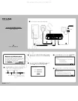
Edimax GS-5208PLG V2, Quick Installation Manual
The Edimax GS-5208PLG V2 is a high-performance Ethernet switch. Make the setup process a breeze with the included Quick Installation Manual. Easily download the comprehensive user manual for free at our website, providing step-by-step instructions and valuable information to maximize your experience with this top-notch product.
Share
Download


Reviews:
No comments
Related manuals for GS-5208PLG V2

H Series
Brand: Parker Pages: 344

KX-HTS Series
Brand: Panasonic Pages: 2

NVR2104-S2
Brand: Dahua Pages: 6

DR-1508P
Brand: Idis Pages: 85
TD-8816
Brand: TP-Link Pages: 2

RNN5
Brand: QUNDIS Pages: 42

RO 1600 PLU
Brand: F.F. Group Pages: 56

ipRocketLink IAD 3086
Brand: Patton electronics Pages: 12

PXI Terminal Block NI TB-2709
Brand: National Instruments Pages: 12

MiniCab
Brand: JAKA Pages: 37

CF Card
Brand: Socket Pages: 28

AC1200R
Brand: Alfa Network Pages: 11

AirBridge VS-YOFIMN-000
Brand: Vivint Pages: 2

FC1202
Brand: Quantum Pages: 108

H820Q Series
Brand: E-Lins Pages: 10
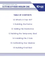
MASLOW CNC
Brand: MAKER MADE Pages: 40

AVP-DE1K-100
Brand: Aegis Pages: 7

WiFi Q2
Brand: Huawei Pages: 52


