P/N: 2900-301566 Rev 1
www.kramerAV.com
USER MANUAL
MODEL:
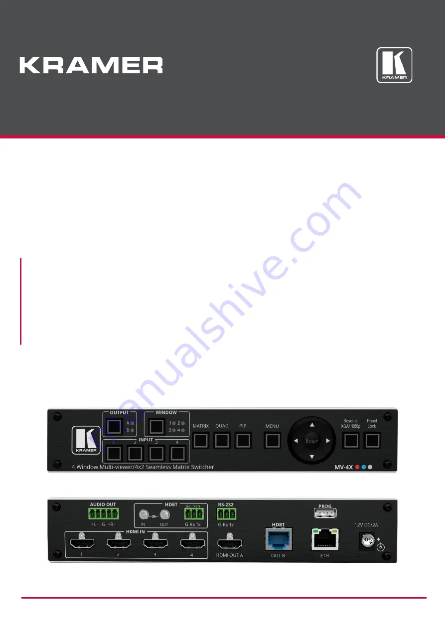
MV-4X 4 Window Multi-viewer/4x2 Seamless Matrix Switcher
Page 1: ...P N 2900 301566 Rev 1 www kramerAV com USER MANUAL MODEL MV 4X 4 Window Multi viewer 4x2 Seamless Matrix Switcher...
Page 2: ...and Operating Via the OSD Menu 10 Operating via Ethernet 21 Using Embedded Web Pages 25 General Operation Settings 27 Defining the Matrix Mode Parameters 31 Defining the Multi View Parameters 34 Defi...
Page 3: ...er high performance high resolution cables to avoid interference deterioration in signal quality due to poor matching and elevated noise levels often associated with low quality cables Do not secure t...
Page 4: ...ddition MV 4X is fully compatible with the HDCP 1 x and 2 3 standards The product offers 2 outputs HDMI and HDBT Users can choose to display any of the four HDMI sources individually in full screen or...
Page 5: ...ble color Logo Support Upload and freely position a graphic logo overlay as well as a boot screen logo Multi view window Setup Intuitive and easy adjustment of window size position and settings User f...
Page 6: ...h buttons with on screen menus or By RS 232 serial commands transmitted by a touch screen system PC or other serial controller Remotely through the Ethernet using built in user friendly Web pages Dire...
Page 7: ...atrix switcher 5 QUAD Button Press to display all four inputs on each of the outputs Layouts are configured via the embedded web pages 6 PIP Button Press to display one input in the background and the...
Page 8: ...at is connected to MV 4X from the HDBT receiver side via HDBT tunneling 14 HDBT RS 232 3 pin Terminal Block Connector Connect to a device for RS 232 HDBT tunneling 15 RS 232 3 pin Terminal Block Conne...
Page 9: ...flow is compatible for the device Avoid uneven mechanical loading Appropriate consideration of equipment nameplate ratings should be used for avoiding overloading of the circuits Reliable earthing of...
Page 10: ...n HDMI acceptor for example a display 3 Connect the HDBT OUT B RJ 45 port to a Receiver for example Kramer TP 580Rxr 4 Connect the AUDIO OUT 5 pin Terminal block connector to balanced stereo audio act...
Page 11: ...owing the RS 232 to control MV 4X Connect an RS 232 terminal block on the rear panel of MV 4X to a PC controller as follows From the RS 232 9 pin D sub serial port connect Pin 2 to the TX pin on the M...
Page 12: ...OSD Menu MV 4X enables controlling and defining the device parameters via the OSD using the front panel MENU buttons To enter and use the OSD menu buttons 1 Press MENU 2 Press ENTER to accept changes...
Page 13: ...INPUT 1 4 IN 1 default PiP PoP or Quad and perform the following actions Menu Item Action Options WIN 1 2 3 4 Source Select the source for the specified window The selected configuration is routed to...
Page 14: ...r Preset 4 see Configuring Recalling a Preset on page 39 Selecting the Window Layout Mode MV 4X enables selecting the window layout for a specific video mode see Setting the Video Mode on page 11 All...
Page 15: ...t to its default settings No default Yes When in PiP PoP Quad mode select a window and perform the following actions Menu Item Action Options Window On Off Enable or disable the currently selected win...
Page 16: ...ick Chroma Key and perform the following actions Menu Item Action Options Chromakey Select On to activate chroma keying When Chroma Key is active the aspect ratio is forced to full screen and the bord...
Page 17: ...ource Select the audio source to pair with video output A IN 1 default IN 2 IN 3 IN 4 Window OUT A Mute Enable or disable muting audio output A On Off default OUT B Source Select the audio source to p...
Page 18: ...Sink Output A Sink Output B User 1 User 2 User 3 User 4 User 1 4 Update Update the USER EDID Copy the desired EDID file EDID_USER_ BIN to the root directory of a USB memory stick Select Yes for a sel...
Page 19: ...1280 720p60 1680 1050p60 4096x2160p24 1280 768p60 1920 1080p24 4096x2160p25 The output resolution is set Setting OSD Parameters MV 4X enables adjusting OSD MENU parameters To set the OSD parameters 1...
Page 20: ...LOGO_USER_ BMP to the root directory of a USB memory stick The new logo graphic file should be 8 bit BMP format with a max resolution of 960 540 Select Yes Insert the USB memory stick into the PROG U...
Page 21: ...ear panel The VGA logo stored in the memory stick uploads automatically Yes No default Logo Settings are configured Setting Ethernet Parameters MV 4X enables defining the Ethernet parameters via the M...
Page 22: ...1 On the front panel press MENU The menu appears 2 Click Setup and define the settings according to the information in the following table Menu Item Function Options Auto Sync Off Set the amount of ti...
Page 23: ...of a few critical system settings and applicable firmware versions To view the Information 1 On the front panel press MENU The menu appears 2 Click Information and view the information in the followin...
Page 24: ...Start Control Panel Network and Sharing Center 2 Click Change Adapter Settings 3 Highlight the network adapter you want to use to connect to the device and click Change settings of this connection Th...
Page 25: ...indow Figure 8 Internet Protocol Version 6 Properties Window 6 Select Use the following IP Address for static IP addressing and fill in the details as shown in Figure 9 For TCP IPv4 you can use any IP...
Page 26: ...4 Figure 9 Internet Protocol Properties Window 7 Click OK 8 Click Close Connecting Ethernet Port via a Network Hub or Switch You can connect the Ethernet port of MV 4X to the Ethernet port on a networ...
Page 27: ...erform the procedure in see Operating via Ethernet on page 21 Ensure that your browser is supported The following operating systems and Web browsers are supported Operating Systems Browser Windows 7 F...
Page 28: ...left side of the screen to access the relevant web page MV 4X web pages enable performing the following actions General Operation Settings on page 27 Defining the Matrix Mode Parameters on page 31 Def...
Page 29: ...enables performing the following actions Setting the Active Operation Mode on page 27 Adjusting Input Parameters on page 28 Adjusting Output Parameters on page 30 Saving Presets on page 31 Setting th...
Page 30: ...igation List The AV Settings page appears see Figure 11 2 Click Inputs tab Figure 13 AV Settings Inputs Tab 3 For each input you can perform the following Change the input name Set HDCP on each input...
Page 31: ...reset the settings to their default values 4 For each input the sliders for each input to adjust the Brightness Contrast Saturation Hue Sharpness H V If you need to make identical adjustments for all...
Page 32: ...ts tab Figure 14 AV Settings Outputs Tab 3 For each output Change the label name Set HDCP to Follow Input or Follow Output 4 Select the audio source for each output HDMI 1 to 4 use the audio from the...
Page 33: ...tion to the right of the Matrix mode turns green 3 Configure the operation mode settings 4 From the Save to drop down box select a Preset 5 Click SAVE A preset is saved Defining the Matrix Mode Parame...
Page 34: ...put output cross point for example between HDMI 1 and OUT B and HDMI 4 and OUT A Figure 15 Matrix Page Inputs are switched to the outputs Defining Switching Fade In and Out Settings To define switchin...
Page 35: ...same video To set Chroma Key Parameters 1 In the Navigation List click AV Settings The AV Settings page appears see Figure 11 2 From the top menu bar select Matrix The Matrix page appears and the gra...
Page 36: ...Configuring Quad Operation Mode In the Quad mode 4 windows are displayed on each output For each window select the video source and set window parameters To set the inputs and outputs in the Quad mod...
Page 37: ...isplay side and clicking or by simply clicking and dragging a window Figure 19 Quad Mode Setting the Position of a Window Mirror the image horizontally using the Mirror slider Enable a border around t...
Page 38: ...ears and the gray indication to the right of the Multi View mode turns green Figure 20 Multi View Tab PoP Mode 4 For each window you can Set Display slider to enable the display of the selected window...
Page 39: ...Operation Mode In the PiP mode up to 4 windows are displayed on each output one window in the background and up to 3 smaller windows to the right For each window select the video source and set windo...
Page 40: ...where 1 is the top layer Next to Size define the size of the window and then click Set the position of the window by entering its exact location H and V by aligning it to a display side and clicking o...
Page 41: ...position routing state window source window layer aspect ratio border and border color rotation state and window state enabled or disabled To set the inputs and outputs see Adjusting Input Parameters...
Page 42: ...ULT to reset the changes made to a selected window to their default parameters The window in the Preset mode is configured Defining the Auto Layout Parameters In the Auto Layout operation mode MV 4X a...
Page 43: ...ng example 2 inputs are active therefore the Single Input and 2 Inputs operation modes are available Figure 26 Multi View Tab Auto Layout Mode Auto Layout modes are defined Managing EDID MV 4X provide...
Page 44: ...gation List The EDID page appears Figure 27 EDID Management Page 2 Under STEP 1 SELECT SOURCE click the required EDID source from the default EDID options the outputs or select one of the User uploade...
Page 45: ...ng EDID is copied to the selected input s Uploading a User EDID file User EDID files are uploaded from your PC To upload a User EDID 1 Click EDID on the Navigation List The EDID page appears 2 Click t...
Page 46: ...grading Firmware on page 45 Restarting and Resetting the Device on page 45 Changing Device Name You can change the MV 4X name To change the device name 1 In the Navigation Pane click Device Settings T...
Page 47: ...appears 3 Open the relevant firmware file The firmware uploads to the device Restarting and Resetting the Device Use the embedded web pages to restart the device and or reset it to its default paramet...
Page 48: ...ure 31 2 Select the Network tab The Network tab appears Figure 33 Device Settings Network Tab 3 Set the Media port Stream service parameters DHCP mode Set DHCP to Off default or On IP Address When DHC...
Page 49: ...ration page The default password is admin By default security is disabled Enabling User Access To enable security 1 In the Navigation pane click Device Settings The General tab in the Device Settings...
Page 50: ...is disabled Changing the Password To change the password 1 In the Navigation pane click Device Settings The General tab in the Device Settings page appears see Figure 31 2 Select Users tab see Figure...
Page 51: ...n signal is lost also set via the OSD menu see Configuring the Setup on page 20 To define auto sync off 1 In the Navigation pane click Advanced The Advanced page appears Figure 37 Advanced Page 2 In t...
Page 52: ...anced The Advanced page appears 2 Set HDR display to enable HDR is enabled View System Status System Status shows the device hardware status If hardware failure occurs or any of the parameters exceed...
Page 53: ...gs page appears Figure 38 OSD Settings Page 2 Define the following parameters Set menu position Top Left Top Right Bottom Right or Bottom Left Set menu timeout or set to Off for no timeout Set menu tr...
Page 54: ...n default image that can be used for testing MV 4X enables the following actions Defining Logo Settings on page 52 Defining Boot Logo Settings on page 53 Defining Logo Settings The OSD logo that appea...
Page 55: ...pane click OSD Settings The General tab in the OSD Settings page appears 2 Select the Logo tab The Logo tab appears 3 Define the Boot Logo parameters Display Enable displaying the logo graphic or dis...
Page 56: ...and select the new logo file and click Open Click UPDATE to upload the new logo from your PC The logo file should be 8 bit BMP format 640 480 resolution Click RESET to remove the current boot logo Boo...
Page 57: ...uttons resolution reset and panel lock buttons Indication LEDs Front Panel Output and window indication LEDs Analog Audio Max Vrms Level 15dBu Impedance 500 Frequency Response 20Hz 20kHz 0 3dB S N Rat...
Page 58: ...river None EDID revision 1 3 Input signal type Digital Color bit depth Undefined Display type Monochrome grayscale Screen size 310 x 170 mm 13 9 in Power management Standby Suspend Extension blocs 1 C...
Page 59: ...ideo identifiers VICs timing formats supported 1920 x 1080p at 60Hz HDTV 16 9 1 1 1920 x 1080p at 50Hz HDTV 16 9 1 1 1280 x 720p at 60Hz HDTV 16 9 1 1 1280 x 720p at 50Hz HDTV 16 9 1 1 1920 x 1080i at...
Page 60: ...erating system 10 0 19042 2 Raw data 00 FF FF FF FF FF FF 00 2D B2 0D 06 31 00 00 00 06 1C 01 03 80 1F 11 8C C2 90 20 9C 54 50 8F 26 21 52 56 2F CF 00 A9 40 81 80 90 40 D1 C0 31 59 45 59 61 59 81 99 0...
Page 61: ...ix nn Command Parameter CR LF Command parameters Multiple parameters must be separated by a comma In addition multiple parameters can be grouped as a single parameter using brackets and Command chain...
Page 62: ...ESS Get image brightness per output Value limits can vary for different devices COMMAND BRIGHTNESS win_num CR FEEDBACK nn BRIGHTNESS win_num value CR LF win_num Number that indicates the specific wind...
Page 63: ...ut_index Number that indicates the specific output 1 HDMI 1 status HPD status according to signal validation 0 Off 1 On Get the output HPD status of Output 1 DISPLAY 1 CR ETH PORT TCP Set Ethernet por...
Page 64: ...put Output For inputs 1 HDMI1 2 HDMI2 3 HDMI3 4 HDMI4 For outputs 1 HDMI 2 HDBT mode HDCP mode For Inputs 0 HDCP Off 1 HDCP On For outputs 2 Follow Input 3 Follow Output Get the input HDCP MODE of IN...
Page 65: ...specific machine or a network in use with DNS feature on COMMAND NAME machine_name CR FEEDBACK nn NAME machine_name CR LF machine_name String of up to 15 alpha numeric chars can include hyphen not at...
Page 66: ...proper settings consult your network administrator COMMAND NET MASK net_mask CR FEEDBACK nn NET MASK net_mask CR LF net_mask Format xxx xxx xxx xxx Set the subnet mask to 255 255 0 0 NET MASK 255 255...
Page 67: ...LR AS scaler sync_speed CR FEEDBACK nn SCLR AS scaler sync_speed CR LF Scaler 1 Sync_speed 0 Disable 1 Slow 2 Fast Set auto sync feature to slow SCLR AS 1 1 CR SCLR AS Get auto sync features Gets the...
Page 68: ...ts 1 HDMI 1 2 HDMI 2 3 HDMI 3 4 HDMI 4 For outputs 1 HDMI 2 HDBT is_native Native resolution flag 0 Off 1 On resolution Resolution index 0 OUT A Native 1 OUT B Native 2 640X480P 59Hz 3 720X480P 60Hz 4...
Page 69: ...z 35 4096X2160P 59Hz 36 4096X2160P 60Hz 37 3840X2160P 50Hz 38 3840X2160P 59Hz 39 3840X2160P 60Hz 40 3840X2400P 60Hz RB Set output resolution VID RES 1 1 1 CR VIEW MOD Set view mode COMMAND VIEW MOD mo...
Page 70: ...lue limits can vary for different devices Value is a property of input connected to current window Changing window input source might cause changes in this value refer device definitions COMMAND W HUE...
Page 71: ...dow associated with the output indicated in the out index parameter COMMAND W SATURATION win_num value CR FEEDBACK nn W SATURATION win_num value CR LF win_num Window number for setting saturation 1 Wi...
Page 72: ...can vary for different devices COMMAND W SRC win_num src CR FEEDBACK nn W SRC win_num src CR LF out_index Number that indicates the specific window 1 Win 1 2 Win 2 3 Win 3 4 Win 4 src Input source to...
Page 73: ...nough space for data firmware FPGA ERR_FS_NOT_ENOUGH_SPACE 11 Not enough space file system ERR_FS_FILE_NOT_EXISTS 12 File does not exist ERR_FS_FILE_CANT_CREATED 13 File can t be created ERR_FS_FILE_C...
Page 74: ...ized dealer from which it was purchased or any other party authorized to repair Kramer Electronics products this product must be insured during shipment with the insurance and shipping charges prepaid...
Page 75: ...nd a list of Kramer distributors visit our website where updates to this user manual may be found We welcome your questions comments and feedback The terms HDMI HDMI High Definition Multimedia Interfa...