OPERETOR’S PANEL
OPERETOR’S PANEL
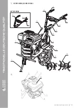
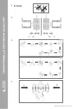
KS 7HP-850А
KS 7HP-850А – first attach the operator’s panel to the steering column using the fixing bolts, then attach
the engine speed control ( see picture 24 in the Appendix).
TRANSMISSION COVER
TRANSMISSION COVER
Attach the transmission cover to the tiller by inserting the fasteners into the corresponding holes (see pic-
tures 29-31 in the Appendix).
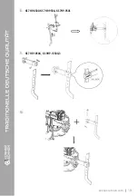
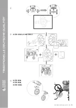
When attaching the blades, always pay attention to the position of the cutting edge of the blades. It should
face the direction of travel of the tiller. Cutters are secured with bolts. The disk is connected to the main
structure using a bolt.
KS 7HP-850A, KS 7HP-1000G
KS 7HP-850A, KS 7HP-1000G
–
see pictures 14-17 in the Appendix.
KS 7HP-950A
KS 7HP-950A
– see picture 25 in the Appendix.
KS 7HP-850A
KS 7HP-850A
– see picture 29 in the Appendix.
KS 7HP-950A
KS 7HP-950A
– see picture 30 in the Appendix.
KS 7HP-950S
KS 7HP-950S
– see picture 31 in the Appendix.
KS 7HP-950S, KS 7HP-1050G, KS 9HP-1350G-3
KS 7HP-950S, KS 7HP-1050G, KS 9HP-1350G-3 – attach the operator’s panel to the steering column
using the fixing bolt (
see pictures 26-28 in the Appendix).
KS 7HP-950S
KS 7HP-950S
– see picture 22 and picture 23 in the Appendix.
KS 7HP-1050G, KS 9HP-1350G-3
KS 7HP-1050G, KS 9HP-1350G-3
– see picture 21 in the Appendix.
1 = 24
8 = 12
2 = 24
9 = 2
3 = 24
10 = 2
4 = 24 5 = 4
6 = 4
7 = 12
Series No. = pcs
1 = 24
8 = 2
2 = 24
9 = 2
3 = 24
10 = 16
4 = 4
11 = 16
5 = 4
6 = 2
7 = 2
Series No. = pcs
FENDERS
FENDERS
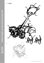
Attach the fenders to the tiller frame by inserting the fasteners into the corresponding holes (see pictures
32-34 in the Appendix).
KS 7HP-850A
KS 7HP-850A
– see picture 32 in the Appendix.
KS 7HP-950A,
KS 7HP-950A, KS 7HP-950S
KS 7HP-950S
– see picture 33 in the Appendix.
KS 7HP-1050G, KS 9HP-1350G-3
KS 7HP-1050G, KS 9HP-1350G-3
– see picture 34 in the Appendix.
3.
For models KS 7HP-1000G, KS 7HP-950A, KS 7HP-950S, KS 7HP-1050G
cutters are assembled in four
sections with four blades each, for model KS 600RTG cutters are assembled in three sections with two
blades each.
KS 7HP-950A
KS 7HP-950A
– see pictures 18-20 in the Appendix.
KS 600RTG
KS 600RTG – The cutting edge of the blade should rotate in the
direction of power, secure the cutters with a 8 × 50 shaft pin and
an R pin;
KS 600RTG
1 = 24
8 = 2
2 = 24
9 = 2
3 = 24
10 = 16
4 = 4
11 = 16
5 = 4
6 = 2
7 = 2
Series No. = pcs
konner-sohnen.com
|
6
Summary of Contents for KS 600RTG
Page 15: ...6 ANWENDUNG ANNEX L ANNEXE ATA AMENT ANEKS 1 2 1 2 5 3 4 KS 7HP 850A konner sohnen com 14...
Page 17: ...7 6 1 2 3 4 5 6 9 8 7 5 4 KS 7HP 1050G KS 9HP 1350G 3 KS 7HP 1050G 3 1 konner sohnen com 16...
Page 18: ...1 2 3 4 5 6 9 8 7 6 4 KS 7HP 1000G 1 4 3 5 6 7 8 9 11 10 2 konner sohnen com 17...
Page 19: ...4 11 1 2 3 4 5 6 9 8 7 7 KS 600RTG 1 6 11 3 9 10 2 14 7 4 12 konner sohnen com 18...
Page 20: ...2 8 9 10 KS 7HP 850A KS 7HP 950A KS 7HP 950S KS 7HP 1050G KS 9HP 1350G 3 konner sohnen com 19...
Page 22: ...B A B A 14 15 16 17 KS 7HP 850A konner sohnen com 21...
Page 23: ...18 19 KS 7HP 950A konner sohnen com 22...
Page 24: ...20 21 KS 7HP 1050G KS 9HP 1350G 3 konner sohnen com 23...
Page 25: ...22 23 KS 7HP 950S konner sohnen com 24...
Page 30: ......


