background image

Chapter  3  SL-Touch  for  SL1000 

3-21


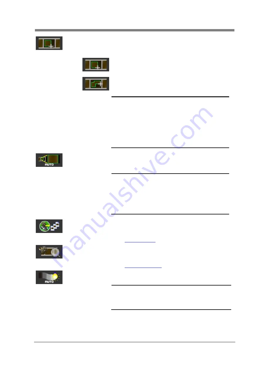
Cropping Mode 
 

The Cropping Mode ("Normal Crop" or "Custom Crop") is 
changed. 


Normal  Crop  : 


The selected area (Cropping Area) is read in an area one 
rectangular. 


Custom  Crop  : 


The rectangular area is added to plurals, and the area is read. 


"Custom Mode" is selected, a mouse cursor becomes a 
"cross" and it can specify two or more ranges. 


NOTE 

!


It returns to the Cropping Area at the Normal 
Mode immediately before when changing 
from the Custom Mode to the Normal Mode. 


When the "Custom Mode" has been 
selected, the setting of "Edit" (Masking etc.) 
becomes invalid. 


The cropping area cannot be added while 
displaying magnification when the custom 
mode has been selected. 


Auto Zoom 
 

To be suitable for the scan window size, the range of the 
Cropping Area selection is automatic zoom position 
corrected. 


NOTE 

!


The magnification becomes the upper bound 
of the optical zoom. 


The magnification returns to the preset value 
set within the Film Selection when the “Auto 
Zoom" button is pressed for 1 second or the 
“Auto Zoom" is pressed while holding the 
“Shift" key on the keyboard. 


Multiple SCAN 
 

The continuous scanning screen of the Roll Film is displayed. 
(The Motorized Roll Film Carrier of the option must be 
installed.) 

 5.2 

Multiple SCAN


Multiple SEARCH 
 

The continuous retrieval screen of the Roll Film is displayed. 
(The Motorized Roll Film Carrier of the option must be 
installed.)   

 5.3 

Multiple SEARCH


Auto Exposure 
 

The image in Cropping Area is adjusted to the proper density 
automatically. 


NOTE 

!


It may not function correctly due to the 
condition of the film (density, contrast, and 
image pattern). In this case, please adjust it 
with Image Adjustment. 


Summary of Contents for SL1000 Digital Film Scanner

Page 1: ...SL1000 Digital Film Scanner User s Guide ...

Page 2: ...International ENERGY STAR Compliance Statement The purpose of the International ENERGY STAR Program is to promote the development and popularization of energy efficient office equipment ...

Page 3: ... of the contents of this section may not correspond with the purchased product Warning and Precautions Symbols WARNING Ignoring this warning could cause serious injury or even death CAUTION Ignoring this caution could cause injury or damage to property Meaning of Symbols A triangle indicates a danger against which you should take precautions This symbol warns against possible burns A dialog line i...

Page 4: ...fire or electrical shock Use only the specified power source voltage Failure to do that could result in a fire or electrical shock Do not use a multiple outlet adapter to connect any other appliances or machines Use of a power outlet for more than the marked current value could result in a fire or electrical shock Do not unplug or plug in the power cord with a wet hand as an electrical shock could...

Page 5: ... the power outlet and then call your authorized service representative If you keep on using it as is a fire or electrical shock could result Connect the power cord to an electrical outlet that is equipped with a grounding terminal CAUTION Do not use flammable sprays liquids or gases near this product as a fire could result Do not let any object plug the ventilation holes of this product Heat could...

Page 6: ... moving this product always hold it by the locations specified in the User s Guide or other documents If the unit falls it may cause severe personal injury The product may also be damaged or malfunction Remove the power plug from the outlet more than one time a year and clean the area between the plug terminals Dust that accumulates between the plug terminals may cause a fire When unplugging the p...

Page 7: ...ntenues dans cette section pourraient ne pas correspondre à votre produit Symboles d avertissement et de précaution WARNING Le non respect de cet avertissement pourrait causer de graves blessures voire un accident mortel CAUTION Le non respect de cette précaution pourrait causer des blessures ou des dommages matériels Signification des symboles Un triangle indique un danger potentiel requérant cer...

Page 8: ... une électrocution Utilisez uniquement la tension d alimentation spécifiée Le non respect de cette consigne risquerait de provoquer un incendie ou une électrocution N utilisez jamais d adaptateur multi prise pour alimenter simultanément d autres appareils ou machines Le branchement à une prise de courant délivrant une tension supérieure aux spécifications risquerait de provoquer un incendie ou une...

Page 9: ...espect de cette consigne risquerait de provoquer un incendie ou une électrocution Branchez le cordon d alimentation à une prise de courant pourvue d une broche de mise à la terre CAUTION Tenez toujours tout produit inflammable liquide gaz et vaporisateur à l écart de l appareil car ces produits posent un risqué d incendie N obstruez jamais les orifices de ventilation de cet appareil avec quelque o...

Page 10: ...jours le tenir aux endroits indiqués dans le mode d emploi ou toute autre documentation Une chute de l appareil risquerait de causer de graves blessures Cela pourrait en outre causer une panne et ou un endommagement de l appareil Veillez à débrancher la fiche du cordon d alimentation de la prise de courant plusieurs fois par an afin de nettoyer les broches de la fiche Toute accumulation de poussiè...

Page 11: ... the system and do not touch any part of the system the manual does not cover NEVER attempt to disassemble or rebuild the system The contents of this manual are subject to change without notice No part of this manual may be quoted reproduced or translated into any other language ...

Page 12: ...ner which has been installed FCC Part 15 Radio Frequency Devices For U S A Users This device complies with Part 15 of the FCC Rules Operation is subject to the following two conditions 1 This device may not cause harmful interference and 2 This device must accept any interference received including interference that may cause undesired operation WARNING This equipment has been tested and found to ...

Page 13: ...shielded interface cable and shielded network cable The use of non shielded cable is likely to result in interference with radio communications and is prohibited under rules We declare under our sole responsibility that the Scanner and options to which this declaration relates is in conformity with the specifications below This declaration is valid for the area of the European Union EU only Tradem...

Page 14: ...lication SL Touch for SL1000 Describes the application SL Touch for SL1000 Chapter 4 Operation Describes operation precautions and procedures and settings for each function Chapter 5 Troubleshooting Describes error and warning messages that appear on the Personal Computer and procedures for eliminating these problems Chapter 6 Maintenance Describes daily maintenance required for satisfactory opera...

Page 15: ... 1 1 SL Touch for SL1000 Setup 3 2 1 1 Trademark Acknowledgments 3 2 1 2 System environment 3 2 1 3 Storage data of Application 3 3 1 4 Installation the Application Software and the Driver Software 3 4 1 5 Update the Application Software and the Driver Software 3 10 1 6 Uninstalling the Application Software and the Driver Software 3 12 2 Application Start Up and Shutdown 3 14 2 1 Application Start...

Page 16: ...sertion 4 5 4 Operating the Roll Film 4 7 4 1 Film Selection 4 7 4 2 Selecting the Film Width 16 mm 35 mm 4 8 4 3 Loading the Roll Film 4 9 4 4 Feeding the Film 4 13 4 5 Rewinding the Film 4 15 4 6 Operation of the A Type Cartridge Adaptor Option 4 16 4 7 Operation of the M Type Cartridge Adaptor Option 4 18 Chapter 5 Troubleshooting 5 1 1 Problems with the Scanner 5 2 2 Troubleshooting 5 3 2 1 Fl...

Page 17: ...xv 1 Major Specifications 7 2 ...

Page 18: ......

Page 19: ...Chapter 1 Precautions for Installation Operation ...

Page 20: ...ctuations Power Source 50 Hz 60 Hz Voltage Fluctuation 120 VAC 10 230 VAC 10 Frequency Fluctuation 50 Hz 3 Hz 60 Hz 3 Hz Be careful not to exceed the capacity of the outlet especially when sharing other appliances from the same outlet The outlet should be located near the unit and be easily accessible so that the Power Cord can be unplugged immediately if necessary NEVER connect any other applianc...

Page 21: ... 1 Precautions for Installation Operation 1 3 1 4 Space Requirements Secure the recommended space shown in the figure below to ensure easy operation and maintenance of the Scanner Standard Fiche Carrier Model ...

Page 22: ...SL1000 User s Guide 1 4 Motorized Roll Film Carrier Manual Roll Film Carrier Model ...

Page 23: ...vessel containing water on the Scanner NEVER drop paper clips staples or other small pieces of metal into the Scanner If this occurs contact your Authorized Dealer NEVER remove the Fixed Outer Cover ALWAYS completely insert the Power Cord Plug into the Power Outlet ALWAYS make sure that the outlet into which the Power Cord Plug is inserted is visible NEVER use this device with Power Cords or USB C...

Page 24: ...nect the Power Cord and the USB Cable When transporting the Scanner contact your authorized dealer CAUTION Never move the Scanner while the Fiche Carrier is pulled out it could cause trouble When the Scanner the Fiche Carrier should be pushed all the way into the Scanner Never hold in a manner other than the identified in the figure Scanner must be held in the area designated in the illustration F...

Page 25: ...Chapter 2 Overview ...

Page 26: ... Carrier Monochrome B W Color Positive Negative etc The optical resolution can be read by the high resolution with 360dpi A4 L or Letter L conversion L landscape The color image of the high resolution can be read by a Color Area CCD Sensor 14 22 Mega pixels It is designed by the power saving corresponding to the regulation Energy Star US ErP Directive EU Special application software SL Touch for S...

Page 27: ...he hand is placed when the image position is fine tuned and the Fiche Carrier is moved 6 Power Switch Turns the Scanner ON OFF 7 USB Connector Connect the USB Cable that is supplied with the equipment 8 Power Cord Socket Plug the Power Cord into this socket 9 Security Slot General purpose security wire for anti theft can be connected through this slot 10 Power Cord Connects the Scanner to the Powe...

Page 28: ...SL1000 User s Guide 2 4 2 2 Roll Film Carrier Option 1 Reel Shaft Roll Film is inserted 2 Take Up Reel Roll Film is wound 3 Guide Roller The Roll Film is guided 1 3 2 3 ...

Page 29: ...Chapter 3 Application SL Touch for SL1000 ...

Page 30: ...computer connected to the Scanner to install the Driver The operator should be completely familiar with basic Windows operations Computer Compatible with IBM PC AT OS Windows 8 1 32 bit 64 bit Windows 8 32 bit 64 bit Windows 7 32 bit 64 bit SP1 or later Windows Vista 32 bit 64 bit SP2 or later CPU INTEL Core i7 or greater Memory 4 GB or greater Hard disk drive 2 GB of available hard disk space Int...

Page 31: ...of the application setting data is saved by each logon user of Windows Various settings and Batch images etc on Preferences NOTE The above mentioned storage data can be changed to the setting of all common users of Windows Please contact authorized service dealer for the setting change ...

Page 32: ... application The following procedure shows the Application Installation for Windows 8 Administrative rights are needed for the Application Installation NOTE Screens may differ slightly depending on the Windows version 1 Load the installation CD ROM in the CD ROM drive of the Personal Computer The Auto Play screen will automatically appear Click Run launcher exe Windows 8 1 or Windows 8 Windows 7 o...

Page 33: ...lick Install SL Touch for SL1000 to begin the installation 3 If the User Account Control screen appears click the Yes button or the Continue Button Windows 8 1 Windows 8 or Windows 7 Windows Vista NOTE This screen may not be displayed depending on the settings of the computer ...

Page 34: ...d Microsoft SQL CE3 5 SP2 is displayed click the Install button NOTE When the above mentioned item has already been installed the Personal Computer this installation screen is not displayed 5 When the Welcome to the InstallShield Wizard for SL Touch for SL1000 screen appears click the Next button ...

Page 35: ...L Touch for SL1000 3 7 6 When the License Agreement screen appears confirm the following messages and click the Yes button 7 Click the Install button 8 When the Windows Security screen appears click Install button ...

Page 36: ...inish button and remove the CD ROM from the Personal Computer IMPORTANT Execute the installation of the device driver when the installation of SL Touch for SL1000 application is completed If the installation of the device driver is not completed the application cannot be started Install the device driver according to the following procedures 11 Connect the Scanner to the Personal Computer with the...

Page 37: ...8 1 and Windows 8 The installation screen is displayed on the taskbar When the progress bar reaches termination and the installation screen disappears the installation completes Windows 7 and Windows Vista Installing device driver software appears When SL1000 Digital Film Scanner Device driver software installed successfully is displayed the driver was installed successfully ...

Page 38: ...rsion is unnecessary Screens may differ slightly depending on the Windows Version 1 Load the installation CD ROM in the CD ROM drive of the Personal Computer The Auto Play screen will automatically appear Click Run launcher exe 2 When the installation screen appears click Install SL Touch for SL1000 to begin the installation 3 If the User Account Control screen appears click the Yes button NOTE Pl...

Page 39: ...ore please install the device driver again If the installation is not completed the application cannot be started Install the device driver according to the following procedures 8 Connect the Scanner to the Personal Computer with the USB cable 9 Turn the Power Switch of the Scanner ON 10 When the scanner is detected and the installation of the device driver is completed the installation of the App...

Page 40: ...ure shows the application and driver uninstall for Windows 8 Administrative rights are needed for the application and the driver uninstall NOTE Screens may differ slightly depending on the Windows Version 1 Confirm the Power Switch of the Scanner is turned OFF 2 From Start menu choose Control panel Click uninstall a program 3 Select SL Touch for SL1000 and then click the Uninstall button 4 When th...

Page 41: ...Chapter 3 SL Touch for SL1000 3 13 5 When the Uninstall Complete screen appears click the Finish button 6 Restart the Personal Computer ...

Page 42: ...he Personal Computer and start Windows 2 Connect the Scanner to the Personal Computer with a USB Cable and turn ON the Power Switch of the Scanner 3 Select the button Start All programs SL Touch SL Touch 4 The application starts in the SCAN Mode after the main screen of SL Touch for SL1000 is displayed NOTE It takes time to start to read the Scanner adjustment value while displaying the opening sc...

Page 43: ...ick button in the upper right corner of the title bar Hold down the application bar located under the title bar until Shutdown Application is displayed Click OK and the application will shutdown SCAN Mode Normal Screen SCAN Mode Full Screen VIEW Mode Normal Screen VIE Mode Full Screen Shutdown Screen Presses the Alt F4 keys on the keyboard ...

Page 44: ... acknowledgment of the next operation after the film stops movie is displayed for a while Response time from the film stop to the still image display can be changed Please contact authorized service dealer for the setting change The image quality of movie can be changed Please contact authorized service dealer for the setting change 2 Cropping Area The area to the output file and the output printe...

Page 45: ...nu bar in this application All are operated with buttons on the toolbar The button displayed on the tool bar can be changed 4 Help Button The Help file is displayed The Help file is also displayed when the F1 key on the keyboard is pressed 5 Roll Film Carrier The Motorized Roll Film Carrier Option is operated 5 1 RollFilmCarrier ...

Page 46: ...orms the zoom operation so that the magnification display is adjusted as long as button is depressed The Scanner shifts to an electronic zoom when the upper bound of the optical zoom is exceeded and does the magnification operation Zoom Out The Scanner does the zoom operation like wide ranging being displayed as long as button is depressed Rotate CCW Whenever the button is pushed the image is rota...

Page 47: ...output to the USB Flash Drive If the button is pressed for a long time when the USB Flash Drive has been installed this will change to the button of Eject USB Eject USB USB Flash Drive can be removed safely Scan to E Mail The image is scanned and it is sent via E mail 3 3 Scan to E Mail Scan to Print Scan to Print2 The image is scanned and it is output to the printer NOTE The range set in Cropping...

Page 48: ... magnified is reduced NOTE When an image is magnified the whole position cannot be moved though the size of cropping area can be changed The reduction image doesn t become smaller than the scan window size It is possible to magnify and to reduce even by the zoom operation of the Touch Panel for the multi touch environment Fit to Window The zoom image is returned to normal size Image Adjustment The...

Page 49: ...dow size the range of the Cropping Area selection is automatic zoom position corrected NOTE The magnification becomes the upper bound of the optical zoom The magnification returns to the preset value set within the Film Selection when the Auto Zoom button is pressed for 1 second or the Auto Zoom is pressed while holding the Shift key on the keyboard Multiple SCAN The continuous scanning screen of ...

Page 50: ...image is automatically corrected NOTE It may not function correctly due to the condition of the film density contrast and image pattern In this case adjust it manually When the inclination is corrected the arrow of the icon changes to the color orange or Pan Window The window of a whole image Pan Window is displayed at the zoom The image in the scan window also follows when the frame of the pan wi...

Page 51: ...the printer is displayed NOTE It returns to a normal display when the preview button was pressed once again while displaying preview The preview display automatically returns to a normal display when the film was moved or specified time passed Refer to Preferences for the specified time setting Output Setting When the scan is output the scan size and the resolution etc are variously set 3 6 Output...

Page 52: ...o select the Custom Profile has been set to OFF on Preferences the switch of Custom Profile becomes invalid 2 Film Type The zoom magnification and the exposure lamp illuminance that is appropriate for the film format are set The proper zoom magnification is set to the aperture card The proper zoom magnification is set to the 35 mm Roll Film NOTE When the Motorized Roll Film Carrier is installed th...

Page 53: ... effective when the Motorized Roll Film Carrier is installed 4 Zoom When Custom is selected in Film Type the zoom magnification is set NOTE The zoom magnification range can be set from 6 8x to 105 0x The zoom magnification range can only be designated when the Film Type is set to Custom Specifying a Zoom Magnification Range is not available for any other Film Selection type When a Custom Profile i...

Page 54: ...and CCW90 9 OK The display colors and the zoom position are determined in accordance with the selected setting NOTE The following settings change into an initial value or the registration value if the film selection is executed Film Type Film Color Monochrome and Color Film Film Polarity Positive and Negative Film Zoom Position Horizontal Flip ON and OFF Rotate None CW 90 CCW180 and CCW 90 Croppin...

Page 55: ...played when it is enabled in E Mail Settings 3 Subject Inputs the Subject Default settings are as follows SL Touch year 4 digits A D the month 2 digits day 2 digits hour 2 digits for 24 hours and minute 2 digits and seconds 2 digits 4 File Name Input the file name 5 Message Input the Message 6 Send Sends the E mail NOTE When a problem is encountered with an E mail transmission an error message is ...

Page 56: ...ss The names and the addresses registered in the Address Book are displayed 2 Add Adds a new E mail address 3 Edit Edit E mail addresses that have been registered 4 Delete Delete E mail addresses that have been registered 5 Select Select an E mail address that has been registered 6 Cancel Cancels the setting and closes the window 5 1 4 3 6 2 ...

Page 57: ...00 3 29 Edit E mail address is registered and edited 1 Name Inputs the address name 2 E Mail Address Inputs the E mail address 3 OK Registers the edited name and address 4 Cancel Cancels the selection and close the window 2 1 3 4 ...

Page 58: ...ted The adjusted value is in real time reflected in the displayed image Standard Mode and Advance Mode can respectively be set by switching the tab Standard Mode 1 Histogram Distribution and the Mean Value of the Histogram of the adjustment area that has been selected are displayed Dark Light 1 2 4 5 6 3 ...

Page 59: ...on range frame Please set it to a proper value 4 The changed setting is settled when OK is pressed the selection range frame disappears and the Cropping Area is displayed 5 When other range is adjusted the Image Adjustment is pressed again and 1 to 4 is executed NOTE A specified frequency of Selected is eight places or less The adjusted image returns to the initial when Image rotation and Skew cor...

Page 60: ...hole area 6 Background The background of the image is eliminated The background elimination of image is decreased The background elimination of image is increased NOTE Background can be adjusted only when using Monochrome Film NOTE Even if Brightness and Contrast are adjusted according to the film an appropriate image density might not be obtained In that case it might be improved by changing illu...

Page 61: ...ue in the image quality adjustment is saved or deleted When the setting is saved the name of the setting is added to the Image Adjustment Setting dropdown list NOTE The following character cannot be used for the setting name and etc It is able to set by common to all custom profile 2 Delete Deletes registered setting When Image Adjustment Setting is selected and Delete is clicked the setting is de...

Page 62: ...he image is made sharper Soft The image is made softer 5 B W Threshold When a black and white binary image is made the threshold is adjusted NOTE When Output setting of the Image type is only B W Manual the binary threshold can be adjusted 6 Hue The hue of the color image is adjusted 7 Saturation The saturation of the color image is adjusted 8 Lightness The lightness of the color image is adjusted...

Page 63: ... lamp are set The exposure lamp is lightened The image lightens for the positive film The image darkens for the negative film The exposure lamp is darkened The image darkens for the positive film The image lightens for the negative film NOTE The usually according to the film and the magnification brightness is adjusted automatically to standard position 1 ...

Page 64: ... registered batch is accessed it selects from the pull down list The Default setting cannot be deleted NOTE The following character cannot be used for the Batch Title and etc Batch saved in another Custom Profile cannot be loaded 2 Batch NOTE The comment is added to the registered batch 3 Delete The registered batch is deleted When Delete is clicked after Batch Title is selected the selected batch...

Page 65: ...form size Landscape Scan image is output by a landscape fixed form size 7 Size The output image size is set It can be selected according to 12 selections A2 A3 A4 B3 B4 B5 17 x 22 Ledger Legal Letter Check and Custom NOTE For Image Type you can only select Gray Scale or B W for A2 B3 and 17 X22 documents When the fixed form size excluding Custom is selected the range of the Cropping Area is output...

Page 66: ...g to shape and the density of the image When the Custom Mode has been selected by Cropping Mode the setting of Edit becomes invalid 11 Watermark Watermark is overlaid to the scan image and it outputs NOTE When OCR was executed because Watermark is overlaid as an image the overlay part might not be recognized 12 Watermark Setting The character the size and the position etc of Watermark are set 3 7 ...

Page 67: ...Chapter 3 SL Touch for SL1000 3 39 File 1 2 3 4 5 6 7 ...

Page 68: ...Possible Profile B Default Impossible Batch 1 Possible NOTE When the Batch Folder is default it becomes SL Touch Folder under My Pictures folder of the logon user of Windows And Batch Folder is able to change in Preferences 3 8 Preferences When repository location has not been selected Save In is displayed by the blank When you set the preservation place save the batch after that If the batch is n...

Page 69: ...set and saved 6 Format The file format is selected It can be selected according to 6 selections BMP bmp TIFF tif JPEG jpg PDF pdf and PNG png NOTE JPEG jpg cannot be selected in case of monochrome binary The multi page file TIFF and PDF cannot be preserved directly When the multi page file is made VIEW Mode and Convert multi page are used for conversion A Searchable PDF file cannot be saved direct...

Page 70: ...etting is enabled before it outputs 4 Fit to printable area of paper size When the image is output the image is magnified or reduced based on the size of the paper 5 Rotate to orientation of paper The image rotates and is printed according to the orientation of the paper 6 Choose paper source by scan size When the selected scan size and the same print size and paper exist in the printer output env...

Page 71: ...mage area is set by value NOTE The magnification is automatically set so that the cropping area can be fit within the image area This is available under the following conditions Function Item Setting Scan Size Excluding Custom Edit None Print Fit to printable area of paper size OFF Both File output and Printer output are available The watermark is generated in the specified area 1 ...

Page 72: ...ser s Guide 3 44 Other 1 Save current setting when batch was saved Save the current setting of Cropping Area when Batch was saved The setting of Cropping Area is restored when the registered Batch is read in 1 ...

Page 73: ...acter and etc cannot be used for the title as a file name of Windows The watermark of each batch is saved and when the batch is newly registered the watermark to which the batch was registered before is succeeded 2 Watermark Text The character of the watermark is set 3 Delete The registered watermark is deleted When Delete is clicked after Watermark is selected the selected watermark is deleted 4 ...

Page 74: ...or Gray Scale of Image Type 9 Angle The angle of the character is set It can be selected according to 3 selections Upward Left to Right Horizontal and Downward Left to Right NOTE When the Position is only Center Upward Left to Right and Downward Left to Right can be selected 10 Position The position of the character is set It can be selected according to 9 selections Top Left Top Middle Top Right ...

Page 75: ...hen the password was forgotten contact the Servicing Dealer The Preferences screen can be displayed via Ctrl K on the Keyboard The password is also required General 1 Application Startup Setting The setting when the application startup is selected Start up with latest setting It starts by the setting when the application was completed before Start up with specified setting It starts regardless of ...

Page 76: ...e application startup is selected 4 Batch When Start up with specified setting was selected Batch when the application startup is selected 5 Launch Film Selection at Startup When the application is started the Film Selection screen is displayed 6 Use operation sound When the application starts and the operation is executed the sound is reproduced NOTE When Windows Media Player is not installed the...

Page 77: ...ode 3 Use the default destination The folder of the default destination which is specified by application is used as parent folder for the batch data preservation NOTE The default folder becomes SL Touch Folder under My Pictures folder of the logon user of Windows 4 Batch Folder When the setting of Use the default destination is OFF the parent folder of the batch data is specified NOTE When the Ba...

Page 78: ...h English French German Italian Japanese Portuguese Russian and Spanish When the Auto Select is selected the language of the application is changed automatically according to the display language of OS NOTE When the Display Language is changed also the language of Help screen changes automatically However as for the language of the User s Guide changing the Display Language it does not change 5 1 ...

Page 79: ...ication ratio is set 4 Magnification Zoom Window The ratio of magnification when Zoom Window was displayed is set 5 Show Preview Image The return time until normal display can be set when the preview screen has been displayed by pressing Preview button It can be selected according to 4 selections 10sec 20sec 30sec and Unlimited 6 Full Screen Change to the Full Screen Mode that doesn t display Wind...

Page 80: ...e scan image is displayed is ON For Scan to File Scan to Print 4 Color Correction The correction of the color reproduction for the color image is set There are three selections available OFF Standard and Color Management 5 ICC Profile The ICC Profile is selected 6 Digital GEM The graininess of the film is decreased It is effective for the image quality reproduction of negative film 7 Manual Switch...

Page 81: ...selected according to 7 selections 5 Minutes 15 Minutes 30 Minutes 60 Minutes 2 Hours 3 Hours and 4 Hours 4 Turn OFF the Scanner The time that should elapse when no operation is performed in Sleep Mode before the Power Supply is turned OFF It can be selected according to 4 selections 60 Minutes 2 Hours 3 Hours and 4 Hours 5 Change Password When the screen of Preference is accessed the password is ...

Page 82: ... name on the Film Selection screen This is where the custom profile name is registered and can be deleted When the custom profile is registered the name of the custom profile is input to Custom Profile column When the custom profile which registered is presented it selects from the pull down list NOTE The following character cannot be used for the custom profile name and etc 2 1 3 4 7 8 5 6 9 10 ...

Page 83: ... Rotation cannot be changed and saved in a Custom Profile unless the Film Type is set to Custom When the Custom Profile is newly registered Batch of the same name as registered Custom Profile is made 4 Film Type The Film Type is selected NOTE When the Custom Profile is newly registered the current setting value in the application software is to be the default value in the Custom 5 Show Roll Film C...

Page 84: ...ded onto the Toolbar list 4 Remove The button displayed on the toolbar is deleted The oriented button on the Toolbar is selected and the button is deleted when Remove is clicked 5 Move Up The position of the selection button on the toolbar is moved on the left When the button is selected on the Toolbar and Move Up is clicked it shifts up one 6 Move Down The position of the selection button in the ...

Page 85: ... is displayed 10 Use Zoom Window Zoom Window is used instead of Pan Window 11 Use Large Icon The size of the icon button in the Toolbar is enlarged by one step 12 Auto Correction The adjusting item executed when the Auto Corrections button is clicked is set It can be selected according to the following 1 Exposure Deskew Focus 2 Exposure Deskew 3 Deskew Focus 4 Exposure Focus ...

Page 86: ...8 OK Customer is registered by the selected setting condition NOTE When Preferences is closed after Custom Setting is executed Film Selection is executed under the registered Custom Setting condition 9 Cancel It ends without registering custom profile 3 5 6 7 4 1 2 8 9 ...

Page 87: ... Password Change The password to display Preferences screen can be changed 1 Old password The password set now is input NOTE The default password is 0000 2 New password The new password is input The password can set only 4 digit numeral 1 2 ...

Page 88: ... for E mail is transmission 3 SSL Sets the SSL enable disable for E mail is transmission 4 Mail Address Sets the sender s mail address 5 SMTP Authentication Sets the SMTP verification enable disable NOTE SMTP Authentication is not available when POP Before SMTP is enabled 6 User ID Sets the SMTP User ID 7 Password Sets the SMTP Password 1 8 2 3 4 5 6 7 9 10 11 12 13 14 15 16 ...

Page 89: ...ets the POP server Login Name 13 Password Sets the POP server Password Other Setting Other settings to which E Mail relates are performed 14 Server Capacity Sets the maximum E mail file size A warning message is displayed when the size of the image data exceeds the maximum value and the E mail transmission is canceled 15 Server Timeouts Sets the time interval for cancelling E mail reception if the...

Page 90: ...open is displayed in the Thumbnail The file is selected by the Thumbnail and the image is displayed in the scan image window by using the drag drop to the window or by performing a double click NOTE It can also be scrolled on the Touch Panel by the flick operation of the Touch Panel When the thumbnail bar is clicked the sorting screen is displayed as follows File Sorting can be set to respectively...

Page 91: ... can be magnified and be reduced by the zoom operation of the Touch Panel for the multi touch environment If the image is edited with other applications it may be unable to read normally 3 Toolbar The application is operated 4 1 Toolbar NOTE There is no menu bar in this application All are operated with buttons on the toolbar The button displayed in the toolbar is not changed in the VIEW Mode 4 He...

Page 92: ...is canceled and it returns to the previous condition Image Adjustment The image quality is adjusted 4 2 Image Adjustment Rotate CCW Whenever the button is clicked the image is rotated 90 degrees counterclockwise Rotate CW Whenever the button is clicked the image is rotated 90 degrees clockwise Deskew CCW When it keeps pressing the button the image is adjusted counterclockwise 45 degrees or less De...

Page 93: ... 4 3 Convert multi page OCR After the OCR operation is executed with PDF File it converts it into Searchable PDF 4 4 OCR E Mail The scanned file is transmitted via E mail 4 5 E Mail Export Export the scanned file 4 6 Export Delete File The scanned file is deleted 4 7 Delete File ...

Page 94: ...ghtness and Contrast are adjusted Procedure of the operation 1 When Selected is selected the selection range frame is displayed in the dotted line of Orange and White 2 The selection range frame is set to the adjusted position 3 When Brightness or Contrast is changed it is affected in the image of the selection range frame Please set it to a proper value 4 The changed setting is settled when OK is...

Page 95: ...67 3 Brightness The brightness of the image is adjusted 4 Contrast The contrast of the image is adjusted NOTE The proper image density can be obtained by adjusting Brightness and Contrast to distribute the Histogram in the whole area ...

Page 96: ...e several minutes per file when OCR is executed When a high resolution is selected the processing time is shortened and the accuracy level increases Therefore it is recommended that the file is saved using a high resolution for all OCR functions 1 File Name The file name of the multi page output is input 2 Format The file type of the multi page output is selected 3 selections are available PDF pdf...

Page 97: ...ward forward When the file is selected with the selection file and Move Up is clicked it moves above one 11 Move Down The position of the selected file is moved to the downward backward When the file is selected with the selection file and Move Down is clicked it moves one the below 12 Delete original file after export After the multi page is exported the selected original file is deleted 13 Expor...

Page 98: ...increases When the OCR is executed it is recommended to preserve it by a high resolution 1 OCR Language Select OCR Language 2 Export File The file PDF file in the batch for the OCR conversion is displayed as a thumbnail 3 Selection File The file selected for OCR conversion is displayed 4 Add All All the files selected for OCR conversion are added 5 Add The file selected for OCR conversion is added...

Page 99: ...tton is clicked the execution of the OCR conversion is canceled NOTE When the OCR conversion is executed it overwrites to the original file When the output is canceled it may take some time to complete the cancellation The file enters the stage of the OCR conversion that was completed before the process was canceled 8 Close The OCR screen is closed ...

Page 100: ...ouch year 4 digits A D the month 2 digits day 2 digits hour 2 digits for 24 hours and minute 2 digits and seconds 2 digits 4 Export File The file file in the batch for the E Mail execution is displayed as a thumbnail 5 Selection File The file selected for the E mail transmission is displayed 6 Add The file to be transmitted via E mail is added It is added to the selection file that the file is sel...

Page 101: ...ated size of all files selected for transmission via E mail is displayed 10 Send Sends the E mail NOTE When a problem is encountered with an E mail transmission an error message is displayed 11 Close The E Mail screen is closed Address Book Refer to Scan to E Mail Edit Refer to Scan to E Mail ...

Page 102: ...ayed by the thumbnail When you click on the thumbnail and the file background changes to orange it indicates the file has been selected for deletion The selection is canceled by clicking on the thumbnail again click or touch 2 Select All Select all files 3 OK Determine the image file and display the Export screen 4 Cancel The export is canceled and the screen is closed 2 3 1 4 ...

Page 103: ...apter 3 SL Touch for SL1000 3 75 Export Files 1 Export to Specify the export destination 2 Save Export the file to the specified destination 3 Cancel The export is canceled and the screen is closed 2 1 3 ...

Page 104: ...deletion is displayed by the thumbnail When you click on the thumbnail and the file background changes to orange it indicates the file has been selected for deletion The selection is canceled by clicking on the thumbnail again click or touch 2 Delete The selected file is deleted 3 Cancel The deletion is canceled and the screen is closed 2 3 1 ...

Page 105: ...he application 5 1 Roll Film Carrier Display Monitor Portrait Screen Display Monitor Landscape Screen Rewind The film is rewound NOTE Only when the Fiche Glass is opened it can be operated When the Fiche Glass is shut this key becomes gray and it cannot be operated Glass Open Glass Close After a few seconds it stops automatically when the film rewind is completed ...

Page 106: ...ed according to the film condition image shape and image density slow fast Film Feeding FWD Direction The film feeding is continued in the forward direction while pressing FWD and stops when FWD is released fast slow Film Feeding REV Direction The film rewinding is continued in the reverse direction while pressing REV and stops when REV is released The function continues when FWD or REV is double ...

Page 107: ...the image is deleted by displaying a White border 2 Centering The center of the image is detected and the image is positioned at the center of the output area 3 Auto Fit The image is enlarged to fit the paper size and output When Custom paper size is selected only the image is output NOTE It is linked with Edit on Output Setting The Edit might not function correctly according to shape and the dens...

Page 108: ...ction adjusting the position of the film 5 4 Alignment when starting the Film Search The screen size is reduced and only Counter display and Film Position adjustment can be operated while continuously scanning In addition the button display changes to Cancel and a continuous scanning can be stopped Continuous Scanning 7 Close The screen is closed NOTE The position where Multiple SCAN is stopped mi...

Page 109: ...trieved the stop time is set It can be set from 2 to 10 seconds every second 3 Set Frame Counter The number of frames image continuously retrieved is set It can be set up to 9 999 frames 4 Counter The number of frames continuously retrieved is displayed 5 Film Position The position of the film stop is adjusted NOTE The stop position of Multiple SCAN Previous and Next changes when the film position...

Page 110: ... Counter display and Film Position adjustment can be operated while continuously retrieving In addition the button display changes to Cancel and a continuous retrieving can be stopped Continuous Retrieving 7 Close The screen is closed NOTE The position where Multiple SEARCH is stopped might vary The film might not normally detect the frame depending on the image condition shape and density When th...

Page 111: ...rder for both Spaces black band of Film Advanced Pitch to be visible please adjust the position of the film In case below both directions are searched Only one side when the Space of Film Advanced Pitch cannot be allocated When it searches in FWD direction in order for the Space black band of Film Advanced Pitch to be visible in the screen right side adjust the position of the film In this case it...

Page 112: ...SL1000 User s Guide 3 84 ...

Page 113: ...Chapter 4 Operation ...

Page 114: ... put anything other than the film on the Fiche Glass Do not place anything heavy on the Carrier Table and prohibit leaning on it Do Not Place hands or fingers in this area when the Carrier Table is pushed into the unit The Fiche Glass shuts when the carrier is pushed into the unit do not place your hand or the fingers in this area Do not put items on the Fiche Glass Do not touch the reel when the ...

Page 115: ...of the Scanner to the ON I Position NOTE When the USB Cable that connects this machine with the computer is not securely connected scanner image data cannot be read 2 2 Turning OFF the Power Switch 1 Quit the application SL Touch for SL1000 2 Press the Power Switch to the OFF O Position NOTE Do not turn OFF the Power Switch when the application is starting in the Scanning Mode Power Switch Power S...

Page 116: ...n of the application This machine shuts down when leaving it without any operation after a continued amount of time when in the Sleep Mode Condition NOTE When returning from Sleep Mode the initialization operation is done It also returns from Sleep Mode if the Manual Switch is pressed once when the Manual Switch Option is utilized It also returns from Sleep Mode if the Fiche Glass is opened and cl...

Page 117: ...rward fully then the Fiche Glass will open NOTE When the Fiche Carrier is pulled out to the maximum position do not put heavy objects on the Carrier Table And prohibit lean against the Fiche Carrier as is could cause damage 2 Insert the film between the Fiche Glasses Aperture Card Place the Card so that the film area is on the right side face up Fiche Jacket Film Place the film so that the title i...

Page 118: ... 6 3 Position the Fiche Film on the Fiche Glass as shown on the figure below 4 Place hands to both sides of the grips of the Fiche Carrier and fine tune the image position Left Grip Right Grip Fiche Film Fiche Film Setting ...

Page 119: ...ode please open the Film Selection Screen Select the film and Show Roll Film Carrier is turned ON You can select 35 mm Roll Film 16 mm Roll Film Either of and Custom NOTE When the Motorized Roll Film Carrier is used it is necessary to turn ON Show Roll Film Carrier Roll Film Carrier cannot be operated when setting is set to OFF ...

Page 120: ... front part of the Guide Roller then reverse the directions of the roller and insert again 2 Change the position of other Guide Rollers in the same manner 4 pieces in total NOTE All of the directions of the Guide Rollers must be in the same orientation 16 mm Setting 35 mm Setting ...

Page 121: ...Be sure to set the film so that its winding direction is clockwise The film will not be correctly rewound if the open reel Roll Film is mounted in the opposite direction Install the Roll Film to the reel so that the square hole of the film and the square face can be adjusted 2 Take hold of the Carrier Handle and pull it forward fully then the Fiche Glass will open ...

Page 122: ...sses NOTE Route the film referring to the figure below 4 Insert the Leading Edge of the Film into the slit in the Take Up Reel and rotate the Take Up Reel two to three turns so that the Film Leader is wound around the Take Up Reel 5 Move the Fiche Carrier so that the image is displayed ...

Page 123: ...and unwind the Leading Edge of the Film NOTE Be sure to set the film so that its winding direction is to be clockwise The film will not be correctly rewound if the open reel Roll Film is mounted in the opposite direction Install the Roll Film to the reel so that the square hole of the film and the square face can be adjusted Knob ...

Page 124: ...le and pull it forward fully the Fiche Glass will then open 5 Insert the Leading Edge of the Film between the Fiche Glasses Plate 6 Insert the Leading Edge of the Film into the slit in the Take Up Reel and rotate the Take Up Reel two to three turns so that the Film Leader is wound around the Take Up Reel 7 Move the Fiche Carrier so that the image is displayed Knob D hole D shape ...

Page 125: ...feeding the film at the same speed The film feeding stops when Stop is clicked at the lock condition NOTE If you feed the film at high speeds pull the Carrier Handle completely forward and then operate the Speed Control Button with the Fiche Glass open The state of the Fiche Glass open close determines the Film Feeding Speed When the film is stopped the motor will stop automatically after a few se...

Page 126: ... Carrier 1 When the forwarding or the rewinding knob is turned the film is advanced or reversed NOTE The knob can be operated when the handle of the Carrier Table is pulled out to maximum which opens the Fiche Glass for film high speed feeding ...

Page 127: ...lick Rewinding and the film is rewound NOTE When Fiche Glass is not open completely Rewinding cannot be operated When the film is finished being rewound the motor will stop automatically after a few seconds Manual Roll Film Carrier 1 Grasp the Carrier Handle and pull it gently out as far as it will go This causes the Fiche Glass to swing up 2 Turn the rewinding knob and the film is rewound ...

Page 128: ...rtridge so that its winding direction is to be clockwise Push the cartridge into a bottom of the Reel Shaft when the cartridge is inserted 2 Insert the film between the upper and lower fiche glass NOTE Set the film as shown in the figure below CAUTION Do not set it in a counterclockwise rolling so that the film surface might get the wound 3 Insert the Leading Edge of the Film into the slit in the ...

Page 129: ...Edge of the Film 2 Insert the film between the upper and lower fiche glass NOTE Set the film as shown in the figure below CAUTION Do not set it in a counterclockwise rolling so that the film surface might get the wound 3 Insert the Leading Edge of the Film into the slit in the take up reel and rotate the take up reel two to three turns so that the Film Leader is wound around the take up reel 4 Ope...

Page 130: ...hole of the Drive Shaft 2 Insert the 2 Pins of the Attachment A in the Notches of the Drive Shaft NOTE The position of Pins is adjusted so that Attachment Pins may surely connect it with notches NOTE The Drive Shaft and the Attachment A are attracted and held together by a magnet When the Attachment A is removed the head of the Attachment A is no longer attracted by the magnet and it detaches Atta...

Page 131: ...lm position of Leading Edge is the lower direction and the hole side of the cartridge housing is the back direction NOTE Be sure to insert the Hook of the Bracket into the square hole of the M Type Cartridge see below drawing NOTE Push the M Type Cartridge until it clicks Hook Hook M Type Cartridge Bracket M Type Cartridge Square Hole Bracket ...

Page 132: ...he Take Up Reel two to three turns so that the Film Leader is wound around the Take Up Reel 7 Operate the Fiche Carrier and rewind the film to an image lead position NOTE Please execute according to the following procedures when the M Type Cartridge is removed 1 Pull the upper part of the M Type Cartridge as arrow direction below 2 Pull out the M Type Cartridge completely as arrow direction below ...

Page 133: ...es of the Drive Shaft NOTE The position of Pins is adjusted so that Attachment Pins may surely connect it with Notches NOTE The Drive Shaft and the Attachment B are attracted and held together by a magnet When the Attachment B is removed the head of the Attachment B is no longer attracted by the magnet and it detaches Attachment B Axis Drive Shaft Attachment B Drive Shaft Notch Notch Pin Pin ...

Page 134: ...ding Edge of the Film into the slit in the Take Up Reel and rotate the Take Up Reel two to three turns so that the Film Leader is wound around the Take Up Reel 6 Operate the Fiche Carrier and rewind the film to an image lead position NOTE Please pull out the reel housing directly as arrow direction below when the 16 mm 35 mm Open Reel is removed 16 mm 35 mm Open Reel 16 mm 35 mm Open Reel ...

Page 135: ...Chapter 5 Troubleshooting ...

Page 136: ...essage appears on the screen of the Personal Computer the Indicator Lamp flashes and scanning stops In this case turn the Power Switch OFF and then back ON Restart the Personal Computer If the same message appears again call your Authorized Dealer with details of the trouble and the Scanner condition ...

Page 137: ... SL Touch The Scanner is disconnected If you are using the Scanner reconnect the Scanner before closing this window If you do not reconnect the Scanner the software will switch to the VIEW Mode Confirm the USB Cable connection is properly connected for the SCAN Mode and close the Warning Screen after the Scanner Power Switch was turned OFF and ON The application restarts with SCAN Mode Close the W...

Page 138: ...nd execute Export SL Touch Save In refers to location that is unavailable It is due to the non detection of USB Memory or the shortage of the memory capacity in the preservation place Please change the preservation setting to the large capacity place or insert the USB Memory etc There is a possibility that the file is not normally preserved before displaying when this message is displayed 2 3 Erro...

Page 139: ...gain Restart the Personal Computer After confirming that the USB Cable is properly connected turn ON the Power Switch of the Scanner again and restart the computer SL Touch Error H W Error Turn OFF the power switch of the Scanner and turn it ON again Restart the Personal Computer After confirming that the USB Cable is properly connected turn ON the Power Switch of the Scanner again and restart the...

Page 140: ...adjust the Scanner Please contact the Authorized Dealer for Service and explain the detail of the error and condition SL Touch Error Failed to read the White Balance Data The White Balance adjustment must be completed It is necessary to adjust the Scanner Please contact the Authorized Dealer for Service and explain the detail of the error and condition ...

Page 141: ...inding Trouble content Action The film doesn t rewind Are the direction where the film is set and the setting of the Reverse Switch correct Confirm the film set direction and the switch setting according to chapter 4 The film winding slows Clean the inside of the guide roller with the cotton pad etc The film stops Is the direction where the film is set correct Confirm the film set direction accord...

Page 142: ......

Page 143: ...Chapter 6 Maintenance ...

Page 144: ...e the Scanner or other electrical equipment Move the Scanner immediately and eliminate the possible cause of malfunction The Scanner is placed on the Power Cord or other cables The Scanner is placed on a cord of other electrical devices 2 If any of the following condition is found turn the Scanner OFF immediately unplug the Power Cord from the outlet and call your local Authorized Dealer The Power...

Page 145: ... the dirt of the fiche glass surface off with a soft cloth 2 Remove the dust with the air blower or the brush Guide Roller It might not be able to wind up the film when dirt adheres in the guide roller 1 Clean the inside of the guide roller with the cotton pad etc NOTE Cleaning kit for the camera like the figure below is recommended as a cleaning tool Fiche Glass Guide Roller Inside of Guide Rolle...

Page 146: ...SL1000 User s Guide 6 4 ...

Page 147: ...Chapter 7 Product Specifications ...

Page 148: ...r It can be selected from 3 modes Resolution 75 100 150 200 240 300 400 600 dpi 600dpi Only the Gray Scale and Monochrome Binary can be set Even A4 or Letter or less can be set Output Size Portrait P Landscape L a Formal Size A2 P L A3 P L A4 P L B3 P L B4 P L B5 P L 17 x 22 P L Ledger P L Legal P L Letter P L Check 8 1 2 x3 2 3 P L b Discretion Size It specifies with the Cropping Area File Output...

Page 149: ...0 35 C Temp Variations 10 C h or less Humidity 15 85 Humid Variations 20 h or less Related Safety Standard All of Areas RoHS compliant North America UL CSA FCC Class A Europe CE CB EN Class B LED Regulation Environment Standard North America Energy Star Europe ErP Directive Options Motorized Roll Film Carrier Kit Manual Roll Film Carrier Kit A Type Adaptor Kit When optional Motorized Roll Film Car...

Page 150: ...your Local Authorized Dealer 1 Your Company Name address telephone number department name floor number machine location etc 2 Model name serial number condition or system s indication s on the display Etc For your reference purpose Model Name SL1000 Serial No Attached Accessories Serial No Serial No Serial No Application SL Touch for SL1000 Version Installation Data Authorized Dealer s Name TEL No...

Page 151: ......

Page 152: ...KO CO LTD The information contained in this manual is subject to change without notice to incorporate improvements made on the product or products the manual covers Manufactured For Konica Minolta by Kyokko Seiko 100 Williams Drive Ramsey NJ 07446 ...

Reviews: