Konica Minolta IC-414 Installation Manual Download Page 7

E-7

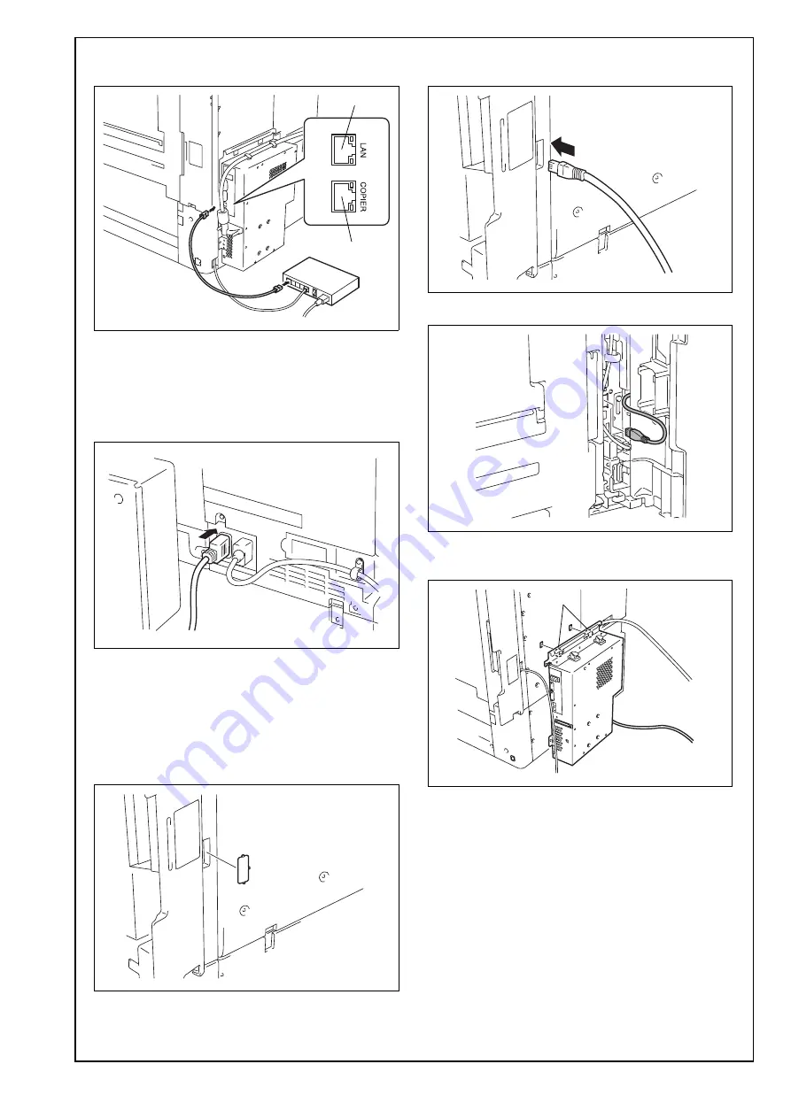
27. Use a network cable to connect port 1 of the 

image controller to the hub (LAN).

28. <110-127 V regions>

Plug the copier and image controller power 
cords into an outlet.
<220-240 V regions>
Connect the image controller power cord to the 
copier. Plug the copier power cord into an outlet.

b: Connecting the copier and image controller 

with the supplied copier LAN cable (cross-
over cable), and connecting the image con-
troller to a hub (LAN)

18. Using nippers, remove the knockout shown in 

the illustration from the copier.

19. Route the supplied copier LAN cable (crossover 

cable) through the notch made in step 18.

20. Connect the cable to the LAN port of the copier.

21. Insert the two image controller tabs into the 

holes on the copier cover.

A4MGIXC028DA

Port 1

Port 2

A4MGIXE072DA

<220-240 V regions>

A4MGIXC029DA

A4MGIXC030DA

A4MGIXC031DA

A4MGIXC032DA

Tab

Summary of Contents for IC-414

Page 1: ...ord B 1 for the wall outlet 1 4 Copier LAN cable crossover cable 1 5 Image transmission cable 1 6 Other accessories 2 A4MGIXC001DB A00HIXC019HA A00HIXE034HA A00HIXC018HA A4MGIXC002DB No Name Shape Q t...

Page 2: ...ds to be installed in advance II Part names Softswitch Lights up when the image controller is running or is ready to be used When turned on the image controller system starts up When turned off the im...

Page 3: ...power cord from the power outlet 2 Remove the cover shown in the illustration from the back of the copier Ten screws 3 Using nippers remove the knockout shown in the illustration from the copier 4 Rem...

Page 4: ...board assy to the copier at the position shown in the illustration Note Insert the connector on the back of the relay circuit board to the connector of the board of the copier 11 Secure the relay circ...

Page 5: ...ed power cord Power cord for Taiwan that utilizes 110V power is not supplied as an accessory part The following procedure is different depending on how the image controller and the copier are con nect...

Page 6: ...rt the two image controller tabs into the holes on the copier cover 24 Screw the image controller to the cover Three supplied screws A and one supplied screw B Note Screw the screws at the bottom and...

Page 7: ...ntroller with the supplied copier LAN cable cross over cable and connecting the image con troller to a hub LAN 18 Using nippers remove the knockout shown in the illustration from the copier 19 Route t...

Page 8: ...transmission cable 24 Connect the copier LAN cable to the port 2 of the image controller 25 Route the image transmission cable and the copier LAN cable through the cable clamps of the image controller...

Page 9: ...imited Note Use a network cable Category 5E or later rec ommended to connect to a computer For details of the connection method see step 18 and subsequent steps in III Installation pro cedures a Conne...

Page 10: ...r to communicate internally through the crossover cable Specifying the copier DHCP setting Utility mode Administrator Settings Network Settings TCP IP Settings IPv4 Settings Auto Input DHCP Settings O...

Page 11: ...then select OK 12 Touch Printer Setup 13 Touch Menu select Yes when Save Changes appears and then select OK 14 When Exit Setup is selected Rebooting sys tem appears and the image controller is restart...

Page 12: ...troller the network interface card in the copier per forms a DHCP request when it is turned on in order to acquire the IP address necessary for communi cating with the image controller Since a DHCP r...

Reviews: