26
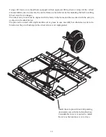
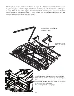
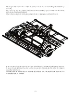
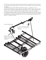
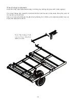
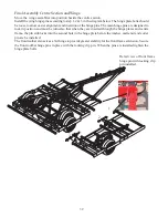
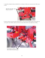
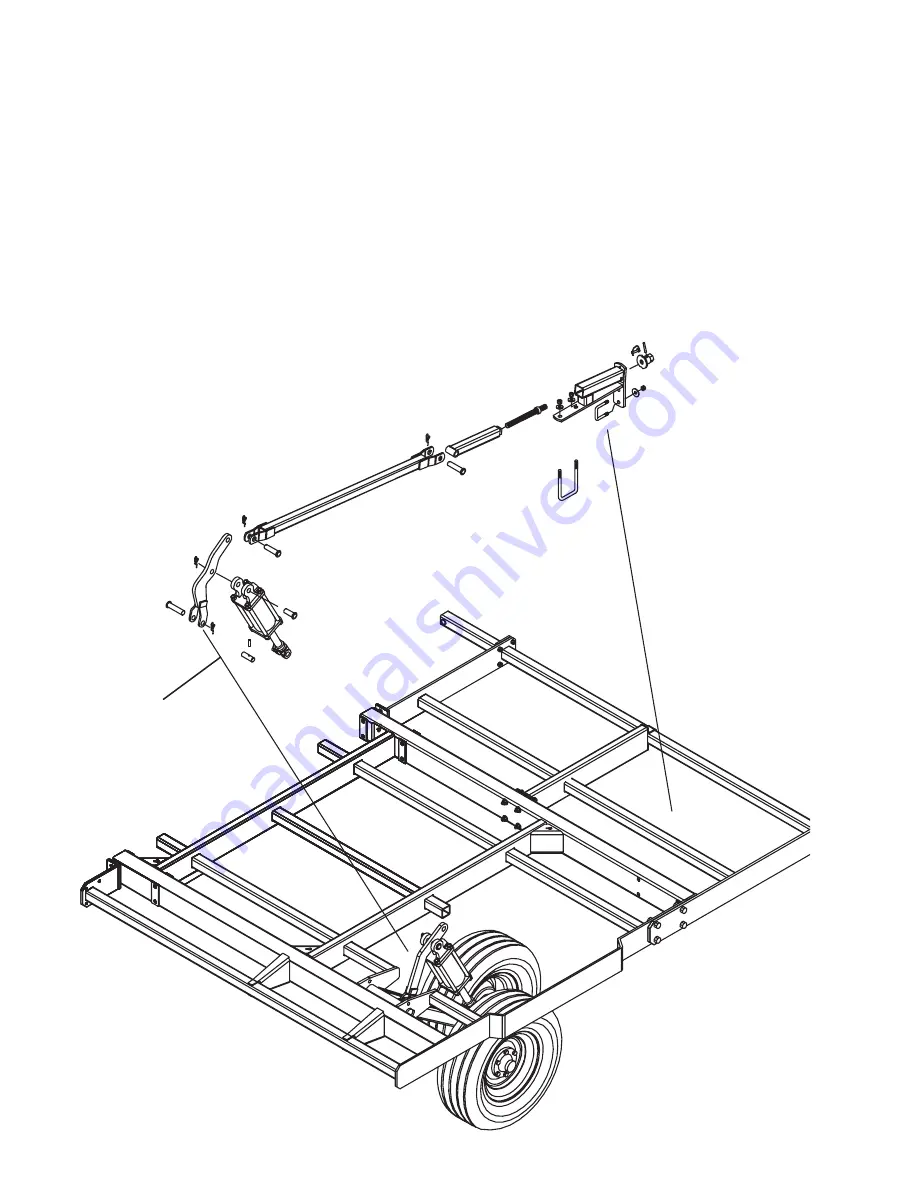
Mount the wing wheel tower and wheel lift cylinder with the pins, bolts and nuts described in the parts
list. The wheel cylinder upright attaches to the upper hole in the wheelarm tube with the pin and clip
pin supplied.
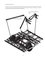
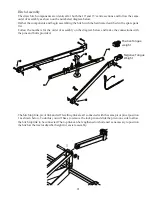
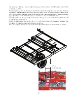
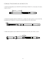
Note that the wing wheel lift cylinders are different sizes. One is 4 x 8 the other is 3-3/4 x 8.
Check the hydraulic layout in order to make sure you install the cylinders on the correct side of the
machine. The 4 x 8 cylinder is installed on the left wing and the 3-3/4 x 8 cylinder is installed on the
right wing as shown below. The ports on both cylinders should face to the front of the machine.
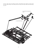
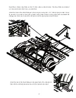
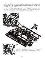
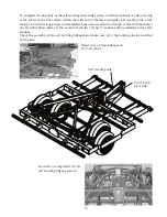
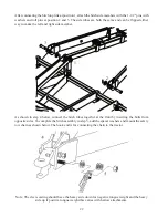
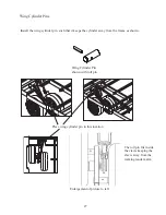
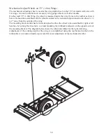
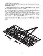
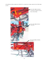
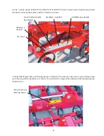
The butt end or top of the cylinder is connected to the wheel upright bar with one of the pins and clip
pins supplied. The rod end clevis connects to the lug on the lower end of the wheel arm so the cylinder
extends and retracts with the rod pointing down. The clevis pin is special and has roll pin to secure it
in place, see next page for details.
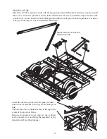
NOTE: The lower
cylinder pin is locked
in place with a roll pin
see page 27
Wheel Cylinder Upright
3-3/4 x 8 Cylinder on Right
Wing and 4 x 8 Cylinder on
Left Wing
Summary of Contents for VIBRO TILL 2900 Series
Page 44: ...44 660 005 033 February 2016...


