Komptec GmbH. KT-90A User Manual
Page 22 of 52
v1.0a; 8 May 2016
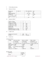
Rotation
Left
For further details, refer to the
Motor’s operating manual
Noise level
86 dB (A)
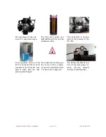
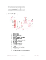
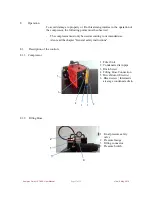
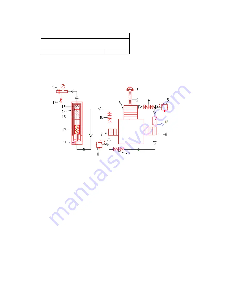
5.5.
Pneumatic Flow Diagram
1.
Air Intake Filter
2.
Air Intake Hose
3.
1st Compressor Stage
4.
Intercooler
5.
1st Stage Pressure Relief Valve
6.
2nd Compressor Stage
7.
Intercooler
8.
2nd Stage Pressure Relief Valve
9.
3rd Compressor Stage
10. Aftercooler
11. Condensation Discharge
12. Condensation Absorber
13. Active Coal Granulate
14. Felt Disk
15. Moisture Absorbtion Granulate
16. Filling Armature
17. Safety Valve
18. Intermediate Condensate Collector and Drain