9
UAB KOMFOVENT we reserve the right to make changes without prior notice
RHP PRO_22-01
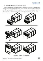
A heat pump assembly consists of a piping system containing refrigerant, compressor, two radiators (condenser and
evaporator) and separate control electronics. If air velocity in the air handling unit is high (> 2 m/s), optional drop elimina-
tors are installed by the condenser and/or evaporator, which prevent condensate from entering other parts of the unit or air
ducts.
LPT
SVD
SVR
LP
ST
6
4
5
DT
7
2
1
3
9
16
15
10
HPT
HP
EXV
13
14
12
11
8
8
8
8
2
11
7
1
14
6
9
17
18
5
4
16
3
12
15
13
10
17
18
19
Fig. 4.
Hydraulic circuit diagram and components of the heat pump
1 – Compressor, 2 – 4-way valve (SVR), 3 – Defrost valve (SVD),
4 – Low pressure transmiter (LPT), 5 – Low pressure pressostat (LP), 6 – Suction gas temperature sensor (ST),
7 – Discharge gas temperature sensor (DT), 8 – Check valve, 9 – Refrigerant coil positioned in the extract airflow,
10 – Refrigerant coil positioned in the supply airflow, 11 – liquid receiver, 12 – Filter-dryer,
13 – Sight glass, 14 – Electronic expansion valve (EXV), 15 – High pressure transmiter (HPT),
16 – High pressure pressostat (HP), 17 – condensate trays, 18 – condensate drainage pipes,
19 – drop eliminator


