1.
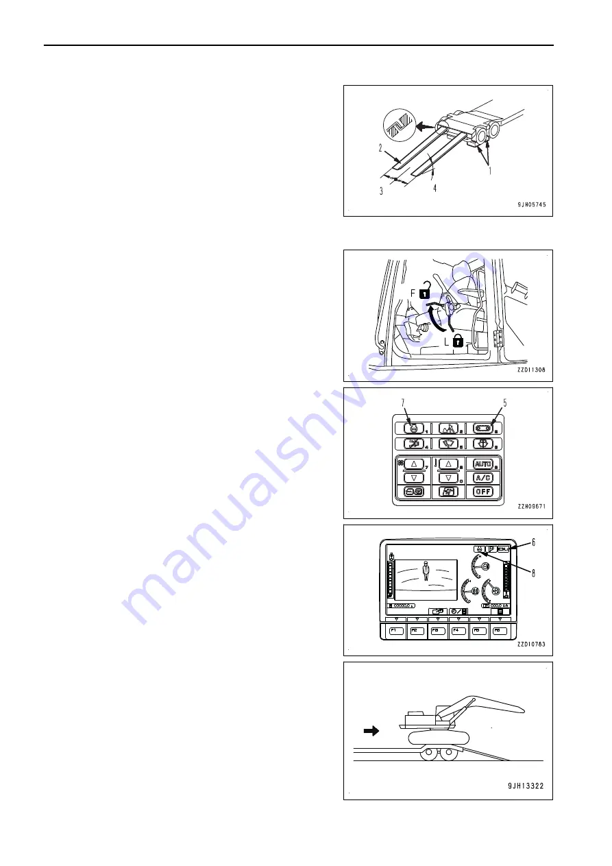
Apply the brake of the trailer securely.
2.
Set chocks (1) to the wheels to secure the trailer.
3.
Set right and left ramps (2) parallel to each other and
equally spaced to the right and left of center (3) of the trail-
er. Make angle of installation (4) a maximum of 15°.
If the ramps bend a large amount under the weight of the
machine, put blocks under the ramps to prevent them from
bending.
4.
Remove the chains and wire ropes fastening the machine.
5.
Start the engine.
Warm the engine up fully in cold weather.
6.
Set the lock lever to FREE position (F).
7.
Push travel speed selector switch (5) to set the travel
speed to low (Lo lights up).
The travel speed (Lo, Mi, Hi) is displayed on travel speed
display (6).
8.
Turn auto-deceleration switch (7) OFF and operate the fuel
control dial to set the engine to low speed.
Each time auto-deceleration switch (7) is pressed, it
switches OFF to ON to OFF in turn.
When auto-deceleration switch (7) is turned OFF, the auto-
deceleration pilot lamp (8) goes out.
9.
Raise the work equipment and move slowly.
10. When the machine is horizontal on the top of the rear end
of the trailer, stop the machine.
TRANSPORTATION
OPERATION
3-248
Summary of Contents for PC360LC-11
Page 2: ......
Page 22: ......
Page 76: ......
Page 344: ......
Page 425: ...SPECIFICATIONS 5 1 ...
Page 429: ...PC360NLC 11 SPECIFICATIONS SPECIFICATIONS 5 5 ...
Page 430: ......
Page 450: ...PC360LC 11 2 Piece Boom PC360NLC 11 2 Piece Boom 2 PIECE BOOM ATTACHMENTS AND OPTIONS 6 20 ...
Page 457: ...ATTACHMENTS AND OPTIONS 17M LONG REACH BOOM AND ARM 6 27 ...
Page 465: ...ATTACHMENTS AND OPTIONS SUPER LONG FRONT BOOM AND ARM 6 35 ...
Page 499: ...REPLACEMENT PARTS 7 1 ...
Page 515: ......


